Transcription of PILOT OPERATED FLOW CONTROL VALVE WITH ANALOG …
1 HIGH PERFORMANCE, TWO-STAGE DESIGN PROVIDING FLOW CONTROL IN A SIMPLE, RUGGED, DEPENDABLE, LONG-LIFE DESIGNWHAT MOVES YOUR WORLDRev. F, June 2014 SERVO VALVESPILOT OPERATEDFLOW CONTROL VALVEWITH ANALOG INTERFACE730 SERIESISO 10372-04-04-92 Moog 730 Series Flow CONTROL Servo ValvesINTRODUCTION2 Whenever the highest levels of motion CONTROL performance and design flexibility are required, you ll find Moog expertise at work. Through collaboration, creativity and world-class technological solutions, we help you overcome your toughest engineering obstacles. Enhance your machine s performance. And help take your thinking further than you ever thought Product Overview 3 Features and Benefits 4 Description of Operation 5 TECHNICAL DATA Standard Response Servo Valves 6 High Response Servo Valves 8 Electrical Data 10 Installation Drawings and Null Adjust Instructions 11 Hole Pattern for Mounting Surface 12 BACKGROUND Null Flow Adjustment 13 Flow Calculation and Null Cut Options 14 Related Products 15 Routine Maintenance Guidelines 16 About Moog 17 ORDERING INFORMATION Accessories and Spare Parts 19 Ordering Code 20 This catalog is for users with technical knowledge.
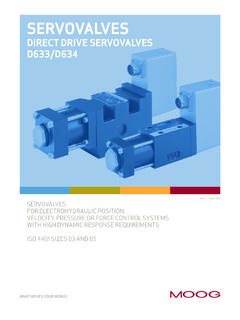
2 To ensure all necessary characteristics for function and safety of the system, the user has to check the suitability of the products described herein. The products described herein are subject to change without notice. In case of doubt, please contact Moog. Moog is a registered trademark of Moog Inc. and its subsidiaries. All trademarks as indicated herein are the property of Moog Inc. and its subsidiaries. For the full disclaimer refer to the most current information, visit or contact your local Moog F, June 2014 TABLE OF CONTENTSPRODUCT OVERVIEWThe 730 Series flow CONTROL servo valves are throttle valves for 3 and preferably 4-way applications. They are a high performance, 2-stage design that covers the range of rated flows from 4 to 57 l/min (1 to 15 gpm) at 35 bar (500 psi) VALVE pressure drop per spool land.
3 The output stage is a closed center, four-way sliding spool. The PILOT stage is a symmetrical double-nozzle and flapper, driven by a double air gap, dry torque motor. Mechanical feedback of spool position is pro vid ed by a cantilever spring. The VALVE design is simple and rugged for de pendable, long life op era tion. These valves are suitable for electrohydraulic position, speed, pressure or force CONTROL systems with high dynamic response requirements. The 730 is ideally suited for applications in the 4 to 57 l/min (1 to 15 gpm) requirements when superior dynamics are a 730 Series Flow CONTROL Servo ValvesINTRODUCTIONTIISI ntrinsically safe VALVE versions are available for use in potentially hazardous environments. Specific models are certified to FM, ATEX, CSA TIIS and IECEx standards.
4 Contact Moog for design 2-stage, with spool and bushing and dry torque motorMounting surface ISO 10372-04-04-92 Maximum operating pressure 210 bar (3,000 psi) standard versionsMaximum Flow 95 l/min (25 gpm) PILOT stage Nozzle-flapperRated flow at pn 35 bar / 4 l/min 10 l/min 19 l/min 38 l/min 57 l/minspool land ( 500 psi /spool land) (1 gpm) ( gpm) ( gpm) ( gpm) ( gpm)Standard step response time for 0 to 100 % stroke 8 ms 8 ms 8 ms 9 ms 16 msHigh step response time for 0 to 100 % stroke 7 ms 7 ms 7 ms ms N/A3 Rev. F, June 2014 Features Benefits2-stage design with dry torque motor Servo valves are compatible with many different fluidsLow friction, double nozzle PILOT stage Symmetrical build provides maximum stability over a variety of conditionsHigh spool CONTROL force Stable consistent flows can be achieved, thus increasing accuraciesHigh dynamics Increased production cyclesRugged, long-life design Reduced maintenance and down timeHigh resolution.
5 Low hysteresis Improved accuracies for close tolerance applicationsSet up at the factory Allows easy installation and setupIntrinsically safe or explosive proof VALVE versions are Servo valves are able to be employed in most hazardous available environmentsField adjustable null bias Servo valves can be adjusted for perfect alignment when interchanging equipmentLoss of electrical signal results in a zero position failsafe This feature allows for predictable, safe operationLarge capacity field replaceable filter Convenient replacement and longer duration between filter changesCarbide, ball-in-hole feedback mechanism Extends lifetime of servo VALVE when compared to slotted spool and sapphire ball designsFEATURES AND BENEFITSMoog 730 Series Flow CONTROL Servo ValvesINTRODUCTION4 Rev.
6 F, June 2014 The 730 Series is proven technology that performs reliably in machines where high performance, stability and accuracy are required. Moog s Mechanical Feedback Valves are designed to provide high reliability and long service life. DESCRIPTION OF OPERATIONThe 730 Series Flow CONTROL Servo VALVE consists of a polarized electrical torque motor and two stages of hydraulic power amplification. The motor armature extends into the air gaps of the magnetic flux circuit and is supported in this position by a flexure tube member. The flexure tube acts as a seal between the electromagnetic and hydraulic sections of the VALVE . The motor coils surround the armature, one on each side of the flexure flapper of the first stage hydraulic amplifier is rigidly attached to the midpoint of the armature.
7 The flapper extends through the flexure tube and passes between the nozzles, creating two variable orifices between the nozzle tips and the flapper. The pressures controlled by the flapper and nozzle variable orifices are fed to the end areas of the second stage spool. The second stage is a conventional four-way spool design in which output flow from the VALVE , at a fixed VALVE pressure drop, is proportional to spool displacement from the null position. A cantilevered feedback spring is fixed to the flapper and engages a slot at the center of the spool. Displacement of the spool deflects the feedback spring which creates a force on the armature/flapper signal induces a magnetic charge in the armature and causes a deflection of the armature and flapper. This assembly pivots about the flexure tube and increases the size of one nozzle orifice and decreases the size of the action creates differential pressure at the spool ends, and the resulting spool displacement causes a force in the feedback wire which opposes the original input signal torque.
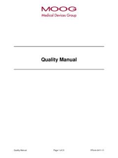
8 Spool movement continues until the feedback wire force equals the input signal 730 Series Flow CONTROL Servo ValvesINTRODUCTION5 Rev. F, June 2014 PBTAF eedback WireLower PolepieceUpper PolepieceArmatureSpoolCoilFlapperConnect orFlexure TubeNozzlesInlet OrificeBushingMagnets (not shown)Electro-hydraulic Servo VALVE Cut-away730 SERIES - STANDARD RESPONSE SERVO VALVES Moog 730 Series Flow CONTROL Servo ValvesTECHNICAL DATA6 Rev. F, June 2014 Sample deviation of rated flow 4 l/min 10 l/min 19 l/min 38 l/min 57 lmin (1 gpm) ( gpm) (5 gpm) (10 gpm) (15 gpm)Rated flow tolerance 10%Step response time for 0 to 100% stroke 8 ms 8 ms 8 ms 9 ms 16 ms Threshold of rated signalHysteresis of rated signalNull shift for T = 38 C (100 F) of rated signal General Technical Data VALVE design 2-stage, with spool and bushing and dry torque motorPilot stage Nozzle Flapper Standard DynamicsMounting pattern ISO 10372-04-04-92 Installation position Any orientation, fixed or movableWeight kg ( lb)Storage temperature range -40 to +60 C (-40 to +140 F)Ambient temperature range -40 to +135 C (-40 to +275 F)
9 Vibration resistance 30 g, 3 axis, 10 Hz to 2 kHzShock resistance 30 g, 3 axisSeal material Fluorocarbon (FKM) 85 Shore A Others upon requestHydraulic Data Maximum operating pressure to ports P, A, B 210 bar (3,000 psi) standard versionsMaximum operating pressure to port T 210 bar (3,000 psi) Rated flow at pN 35 bar/spool land (500 psi/spool land) 4 l/min 10 l/min 19 l/min 38 l/min 58 l/min (1 gpm) ( gpm) (5 gpm) (10 gpm) (15 gpm)Maximum flow 95 l/min (25 gpm)Null adjust authority Greater than 10% of rated flowHydraulic fluid Hydraulic oil as per DIN 51524 parts 1 to 3 and ISO 11158. Other fluids on request. Temperature range -40 to +60 C (-40 to +140 F) Recommended viscosity range 10 to 85 mm2/s (cSt) Maximum permissible viscosity range 5 to 1,250 mm2/s (cSt)Recommended cleanliiness class as per ISO 4406 For functional safety 17/14/11 For longer service life 15/13/10 Recommended filter rating For functional safety 10 75 (10 m absolute) For longer life 5 75 (5 m absolute)Static and Dynamic Data (at 3,000 psi)730 SERIES SERVO VALVES - STANDARD RESPONSE SERVO VALVESMoog 730 Series Flow CONTROL Servo ValvesTECHNICAL DATA7 Rev.
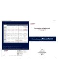
10 F, June 2014 Full Amplitude Step Response100% Step Plot 1 = 730-100B, 730-101B, 730-102 BPlot 2 = 730-103 BPlot 3 = 730-104B-2+2-410012008060204001101001122 33-8-10-6 Phase Lag (Degrees)Amplitude Ratio (Decibels)Frequency (Hz)Reduced Amplitude Standard Frequency ResponsePlot 1 = 730-100B, 730-101B, 730-102 BPlot 2 = 730-103 BPlot 3 = 730-104B-2+2-41001200806020400110100-8-1 0-6 Phase Lag (Degrees)Amplitude Ratio (Decibels)Frequency (Hz)Full Amplitude Standard Frequency ResponsePlot 1 = 730-100B, 730-101B, 730-102 BPlot 2 = 730-103 BPlot 3 = 730-104B1121261661020406080100123 Stroke (% of Rated Signal)Time (ms)730 SERIES - HIGH RESPONSE SERVO VALVES Moog 730 Series Flow CONTROL Servo ValvesTECHNICAL DATA8 Rev. F, June 2014 Sample deviation of rated flow 4 l/min 10 l/min 19 l/min 38 l/min (1 gpm) ( gpm) (5 gpm) (10 gpm) Rated flow tolerance 10%Step response time for 0 to 100% stroke 7 ms 7 ms 7 ms ms Threshold of rated signalHysteresis of rated signalNull shift for T = 38 C (100 F) of rated signal General Technical Data VALVE design 2-stage, with spool and bushing and dry torque motorPilot stage Nozzle Flapper Standard DynamicsMounting pattern ISO 10372-04-04-92 Installation position Any orientation, fixed or movableWeight kg ( lb)Storage temperature range -40 to +60 C (-40 to +140 F)Ambient temperature range -40 to +135 C (-40 to +275 F)