Transcription of Piping Evaporative Condensers
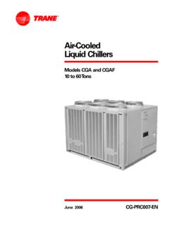
1 Piping EvaporativeCondensers Bulletin 131 AEvaporative Condensers are used in refrigerationsystems as an efficient means of heat rejection. Theirinstallation and specifically the installation of thepiping to and from the Evaporative condenser has adirect effect on their operation and the overall energyefficiency of the refrigeration system. In this manual,we will explore the principles of Piping evaporativecondensers, beginning with single Condensers andexploring multiple condenser installations as well asthermosiphon and sub-cooling Piping Condensers came into common use fornearly all refrigeration systems because of theiroperating advantages over the combination of coolingtowers and Condensers . They, of course, have alsoreplaced the old "once through" water cooledcondensing systems which are obsolete todaybecause of the restrictions on the unlimited use ofwater coupled with its high , shell and tube condensing systemsperformed the same job of condensing the hotdischarge gas into a saturated liquid as evaporativecondensers; a small difference in the operatingcharacteristics, namely pressure drop, requires somemodification in the refrigerant Piping hookup to andfrom the Evaporative condenser.
2 These changes areparticularly important when dealing with multiple unitinstallations. In order to understand why the pipinghookup is important, let's first take a brief look at thebasic design differences of the two types of condensersto see why there is a difference in the pressure shell type refrigerant Condensers allow therefrigerant to flow around and condense on the outsideof the water tubes. (See Figure 1)The refrigerant flowis almost entirely unimpeded resulting in a very low ornearly zero pressure drop through the , most Evaporative Condensers (See Figure2)utilize some type of serpentine coil design where thehot refrigerant gas enters the top of the coil travelingback and forth through several rows as it is cooled andchanged from a hot superheated gas to a saturatedliquid. This longer travel path generally produces asmall pressure drop which, though insignificant to theoverall operation of the refrigeration system, doesrequire proper attention be given to the condenserpiping.
3 Most of this attention needs to be focused onthe liquid drain line from the outlet of the evaporativecondenser to the high pressure receiver. The reasonsfor this will be explained in the sample pipe describedlater Discharge LineThe condenser can be piped into a system with eitherone or multiple compressors. The compressordischarge line should be sized in consideration of thelength of the run from the compressor to thecondenser, and the total amount of pressure drop thatis to be allowed. Good practice would normally permita pressure drop corresponding to a 1 F (.5 C)condensing penalty, per 100 equivalent feet (30m).The ASHRAE Handbook of Fundamentals uses thiscriteria as the basis of their capacity tables fordischarge lines. For reference, Table 1 is included hereto show the line carrying capactity in TR (kW) ofrefrigeration for the most common refrigerants in bothsteel pipe and copper is based on a line friction pressure drop of a 1 F(.)
4 5 C) change in the saturation temperature per 100equivalent feet (30m) of most installations use of this table will provide anegligible difference between the actual compressordischarge pressure and that at the entrance to any system, whether it is new or old, measurablyhigher pressure drops in the discharge line need to betaken into consideration in sizing the condenser andcompressor. For example, if there was to be an 8 psi(56kPa) pressure drop in discharge line of an NH3system, it would amount to about a F ( C)reduction in saturation temperature at the means that either the condenser should beincreased in size approximately 15 percent or it mustLIQUIDDISCHARGEGASWATEROUTWATERINLIQ UIDDISCHARGEGASF igure 1 Figure 2 TYPICAL SHELL AND TUBE WATER COOLED CONDENSERTYPICAL Evaporative CONDENSER COIL 2002 EVAPCO, accepted that the compressor discharge pressurewill be 8 psi (55kPa) higher than design.
5 Special consideration should be given to discharge linesizing when centrifugal compressors are being machines have more critical headcharacteristics that may necessitate larger line Drain Line Single CondensersNow let's consider the recommended Piping for asingle condenser illustrated in Figure 3. This figure shows a single coil Evaporative condenserproperly piped into a system with a top inlet highpressure receiver. The compressor discharge linecontains a purge valve at the high point and a servicevalve. The liquid drain line is properly sloped and arelief valve from the condenser. It contains a purgevalve in the horizontal portion, and a service valve hasbeen installed in the vertical portion. The receiver isfitted with another purge connection and relief valve. The liquid drain line from the condenser to thereceiver as was noted earlier, must receive the mostcareful attention.
6 It is fundamental that this line bedesigned to allow the liquid to flow freely, by gravity, tothe receiver. The sizing of the line depends uponwhether it runs directly from the condenser to the topof the receiver or whether it is trapped if it entered thebottom of the an untrapped situation as shown, the liquid drainline must be sized so that this low velocity will insurethere is sewer drainage in the line. (Figure 4) That is,there is space above the liquid flow for free vapormovement in either allows the pressure in the receiver to be equalizedwith the pressure at the coil outlet and thus will allowfree liquid flow from the condenser outlet to thereceiver. The liquid drain line should also be pitched atleast 1/4 inch per foot (20mm per meter) toward thereceiver to facilitate this flow. 3 NOTES:1. CAPACITIES SHOWN ARE TONS (kW)2.
7 STEEL PIPE 1-1/2 INCH (38mm) AND SMALLER SCH. 80, 2 INCH (50mm) AND LARGER SCH. 40. 3. CAPACITIES BASED ON THE FOLLOWING CONDITIONS:R-22, R-134a, R-407c, R-410a, AND R-507: 40 F ( C) SUCTION, 105 F ( C) CONDENSINGR-717: 20 F ( C) SUCTION, F ( C) CAPACITIES BASED ON LINE FRICTION PRESSURE DROP PER 100 FEET (30m) OF EQUIVALENT PIPE LENGTH WHICH CORRESPONDS TO A 1 F (.5 C)CHANGE IN SATURATION TEMPERATURE. THIS LINE FRICTION PRESSURE DROP PER 100 FEET BY REFRIGERANT ISR-22: PSI ( KPa)R-407c: PSI ( KPa)R-507: PSI ( KPa)R-134a: PSI ( KPa)R-410a: PSI ( KPa)R-717: PSI ( KPa)COMPRESSORDISCHARGE LINEPURGE VALVE SEEPURGING SERVICEVALVESLOPE 1/4" PER FOOT(20mm PER METER)RELIEFVALVESERVICE VALVEIN VERTICAL LINERELIEFVALVELIQUID LINETO SYSTEMRECEIVERPURGEVALVEPURGEVALVET able 1 Figure 3 NOMINAL SIZER-134aR-22R-407CR-410AR-507R-717 STEELCOPPERSTEELCOPPERSTEELCOPPERSTEELCO PPERSTEELCOPPERSTEELCOPPERSTEEL1 (25)1-1/8 (29/26)4 (17)6 (26)7 (30)9 (37)6 (25)9 (38)8 (36)13 (57)5 (21)8 (34)15 (64)1-1/4 (32)1-3/8 (35/32)10 (44)10 (45)14 (62)15 (64)12 (52)15 (66)18 (76)23 (99)11 (46)14 (59)39 (168)1-1/2 (40)1-5/8 (41/38)15 (65)16 (71)22 (93)23 (101)18 (79)24 (105)27 (116)36 (156)16 (69)22 (93)59 (252)2 (50)2-1/8 (54/50)29 (126)34 (146)41 (178)49 (209)43 (184)50 (217)63 (270)75 (321)37 (161)44 (191)113 (487)2-1/2 (64)2-5/8 (67/63)47 (201)60 (258)66 (284)85 (368)68 (294)
8 89 (382)100 (430)131 (565)60 (256)78 (337)180 (776)3 (80)3-1/8 (79/75)83 (355)96 (411)116 (501)136 (587)120 (519)141 (608)176 (760)209 (900)105 (453)124 (536)318 (1370)4 (100)4-1/8 (105/99)168 (723)200 (862)237 (1021)284 (1225)245 (1056)295 ( 1271)359 (1545)436 (1878)214 (921)260 (1119)648 (2792) compressor Discharge Line for Steel Pipe & Copper Tubinginches (mm)When the liquid drain line is trapped, as in Figure 5, afree flow of vapor and hence pressure equalizationbetween the receiver and coil outlet cannot occurthrough the liquid line. In this case a separate linemust run from the top of the receiver to the outlet ofthe coil to serve as an since the liquid drain line is handling only liquid itcan be reduced in size somewhat. In this case, the linesize should be based on the values listed in table Condensers are often provided withoversized outlet connections.
9 In this case the drain linecan be reduced from the size furnished by the factoryand still meet the criteria. It is permissible to reducethe line as shown in Figure 6, but it is recommendedthat it be done in the vertical portion of the line. If usingthis method, then the installation of shut off or servicevalves is preferred in the vertical portion of the line,and at least a foot below the horizontal portion. An often used but not preferred alternate method(Figure 7)of reducing the condenser outlet size mayalso provide satisfactory operation. After the purgevalve, an eccentric reducermay be installed in thehorizontal portion of the line. Also, an angle type shut-off valve may be installed provided the seat designallows complete drainage from the bottom of thehorizontal pipe. In this arrangement the drain line should always besized for two phase sewer flow regardless of thehookup.
10 It is recommended, for best results, that thevelocity be kept as low as possible, particularly if anangle valve is installed. 4 PURGEVALVE12" MINIMUMSERVICEVALVECONCENTRICREDUCERCOMP RESSORDISCHARGE LINEPURGE VALVE SEE PURGING SERVICEVALVESLOPE 1/4" PER FOOT(20mm PER METER)RELIEFVALVESERVICE VALVEIN VERTICAL LINERELIEFVALVERECEIVEREQUALIZERPURGEVAL VEPURGEVALVELIQUIDLINETOSYSTEMF igure 5 Figure 6 RECOMMENDED METHOD OFREDUCING LINE SIZE IN VERTICAL PIPESEWER DRAINAGEF igure 4 PURGEVALVEANGLE VALVE WITHSEAT INSTALLEDTO PROVIDEUNOBSTRUCTEDFLOWECCENTRICREDUCERL INE SIZED FORTWO PHASE SEWER FLOWF igure 7 ALTERNATE METHOD OFREDUCING LINE SIZE IN HORIZONTAL PIPET rapped Liquid LineNOTES:1. CAPACITIES LISTED IN TONS (kW). 2. STEEL PIPE 1-1/2 INCH (38mm) AND SMALLER SCH. 80, 2 INCH (50mm) AND LARGER SCH. Liquid Drain Line for Steel Pipe & Copper TubingTwo Phase Sewer FlowThere are a lot of Condensers operating with the drainlines reduced in the horizontal portion by concentricreducers and with horizontal valves as well.