Transcription of Piston Distributor Lubrication Using Oil - Lube Systems of ...
1 LUBRIQUIP, INC., 1998. All Rights DistributorLubricationUsing OilInjecto-Flo Piston Distributor System ComponentsLUBRIQUIPBY Bulletin 12120 Product Specs and OrderingRevised August 2000R12120iACCESSORIEST able of ContentsIntroduction/Components/Features .. 1 System Operation .. 2 Hand Operated Pump .. 3 Air Operated Pumps .. 4 Electric Motor Driven Pumps .. 5 - 8 Piston Distributors .. 9 -11 Manifolds and Manifold Accessories .. 11 - 12 Piston Distributors (Push to Connect) ..13 Piston Distributors (Bearing Point) .. 14 Piston Distributors (Post Fire) .. 15 - 16 Electrical Controls.
2 17 - 21 Pressure Switch .. 22 Pressure Gauges .. 22 Filters .. 22 Anchor Blocks .. 23 Manifolds .. 24 Tube Fittings (Threaded) .. 25 - 26 Tube Fittings (Push to Connect) .. 27 - 28 Tube Clips .. 28 Tubing .. 28 Hose Assemblies .. 28 Lubriquip Systems .. 29 Index .. 30 RInjecto-Flo Piston Distributor System ComponentsiiPage 112120 Injecto-Flo Piston Distributor System ComponentsInjecto-Flo Piston Distributor Systems utilize one of threetypes of pumps: A single-stroke hand-operated pump; asingle-stroke, air-operated pump: or a continuous flow,electric motor driven pump. Pump output is delivered topiston distributors which dispense precise amounts oflubricating oil to the bearing points.
3 Air-operated pumpsrequire a solenoid-operated air valve and controller toactivate the pump. Electric motor driven pumps use anelectric motor and built in, or remote timer device to activatethe pump. The Piston Distributors are mounted in manifoldssupplied by Lubriquip. The bearing point type mount at thebearing point and require no manifold. Various accessoriesare available to simplify installation. An optional pressureswitch or gauge may be added at the pump outlet port, ifdesired, to monitor pump COMPONENTSP umpsPositive displacement, hand-operated pumps, air-operatedpumps and electric motor driven pumps are available withmetal or plastic reservoirs allowing a system to be designedprecisely for the application Solid-state timer can be set to control pump run durationand to initiate lube cycles at intervals from 30 seconds to 32hours.
4 Other optional controllers schedule lube intervals ontime, or machine usage. The LC-1000, can control andmonitor pump run duration based on input from a and Piston DistributorsOne manifold can distribute lubricant to as many as 10 lubepoints. Piston Distributors come in seven outputs to meetvarious lube requirements. Bearing point Piston distributorsare fed directly from the pump through individual branch linesand do not require a , Hardware, Fittings andAccessoriesInjecto-Flo Piston Distributor Systems utilize metric tubing(metal or nylon) and brass fittings. Adapters are available toallow the use of inch size tubing where Piston Distributors offer an efficient method ofapplying lubricant, resulting in less machine downtime,increased productivity, and a safer work Systems go beyond these advantages to provide:nEasy system design and components and payback!
5 Savings in lube maintenance;man-hours usually pay for the system within the first reservoir available for heavy-duty construction internally vents system pressure,requiring no extra cost external vent , air and electric powered pumps available withseveral reservoir sizes to fit a wide variety of and low level switches meet EEC requirements(CE mark compliance).SYSTEM DESCRIPTIONThe Injecto-Flo Piston Distributor System is a single-line,parallel type. When the solid-state timer, controller, oroperator activates the pump, lubricant is forced down asingle main line to manifolds, and from there throughindividual Piston distributors and lines to the lube bearing point Piston distributors are used, manifolds arenot required.
6 Instead, the single main line branches intoindividual lines feeding the bearing point Piston both cases, the Piston distributors dispense lubricant to abearing. Once lubricant is dispensed at the lube points,system pressure is vented by the pump. This allows thepiston distributors to prime themselves in preparation for thenext Lubrication 2 Injecto-Flo Piston Distributor System Components12120 SYSTEM OPERATIONAs shown in Figure 1, when the operator actuates thehandle, or when the solenoid-operated air valve, or electricmotor receives a signal from the timer, the pump is pump dispenses lubricant either into the mainline tubingwhich distributes the lubricant to the manifolds, feeding eachpiston Distributor or lines supplying bearing point pistondistributors.
7 Each of the Piston distributors is sized tomeasure and dispense the proper amount of lubricant basedon the requirements of the bearing. Details of the operationof each component are included in this components are functionally interchangeable withother commonly used single-line, parallel Piston distributorsystems. Mounting dimensions of the components are veryclose to those of other Systems , and for some componentsthere is a direct interchangeability in form and fit as well Piston Distributor Systems are ideal for small to largemachine tools and other equipment requiring economical,intermittent.
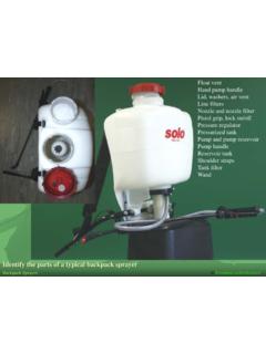
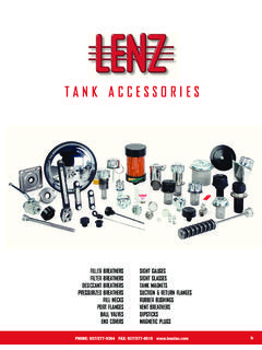
8 Oil PAGE 3 ELECTRICMOTORPUMPSEE PAGES5 THROUGH 8 BEARINGTUBING AND HOSESEE PAGE 28 BEARING POINTPISTONDISTRIBUTORSSEE PAGE 14 MANIFOLDSEE PAGE 11 & 24 Piston DISTRIBUTORSSEE PAGES 9 THROUGH 13 Figure 1 Injecto-Flo Piston Distributor System DiagramANCHOR FITTINGSSEE PAGE 23 FITTINGS AND ADAPTERSSEE PAGES 23-28 FILTERSEE PAGE 22 SOLENOID-OPERATEDAIR VALVEAIR-OPERATEDPUMPSEE PAGE 4 Page 312120 Injecto-Flo Piston Distributor System ComponentsHAND-OPERATED PUMP (HO-1)DESCRIPTION / OPERATIONThe HO-1 hand pump (Figure 2) is a positive displacement,single stroke pump that delivers up to 13cc (.)
9 80 ) againsta maximum system pressure of 30 bar (435 psi). As thehandle is pulled back, a return spring is compressed andpump flow is delivered to the system mainline. As mainlinepressure builds, the individual Piston distributors dispense ameasured volume of lubricant to the bearing points. Whenthe handle return to the rest position, the pump Piston movesback to the prime position. Simultaneously, mainlinepressure is vented allowing the Piston distributors to re-primein preparation for the next lube Outlet Nut 6mm Tube435-702-466 Replacement Outlet Ferrule 6mm Tube435-702-421 Figure 2 Hand-Operated PumpFigure 3 DIMENSIONSmm/(inches) ( ) (.
10 26)6mm TUBE(M12 x 1) ( )SPECIFICATIONSM aterial: .. Steel and Aluminum Pump, TranslucentPolypropylene ReservoirOutput (Max.): .. 13cc ( ) per strokePressure (Max.): .. 30 bar (435 psi)Relief valve protectedOil Viscosity: .. ISO 50 - 1000 (250 - 5000 SUS)Rest Time Between Cycles (Min.): .. 15 secondsTime at Pressure (Min.): .. 5 secondsNote: Due to the single stroke operation of this pump,total system discharge volume must not exceed 50% ofpump delivery ( ). ( ) ( ) (.67) ( ) ( ) ( )Ordering InformationTable 1 ReservoirCapacityMaterialPart Number1 liter (2 pt) ( )Page 4 Injecto-Flo Piston Distributor System Components12120 Figure 4 Air Operated PumpORDERING INFORMATIONT able 3 RESERVOIRCAPACITYPART liters (Pt)MATERIALNUMBER2 (4)Plastic126-400-1003 (6)Plastic126-400-1205 (10)Metal126-400-130 DBFCAF igure 51/8 BSPAir6mm TUBE(M12 X 1) (.