Transcription of Piston Pump Catalog - Continental Hydraulics UK Ltd
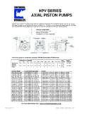
1 HPV SERIESAXIAL Piston PUMPSHPV SERIESAXIAL Piston PUMPSINDEXTHEORETICALMAXIMUMVOLUMETRICFL OW@MODELCONTINUOUSFLANGEPAGESDISPLACEMEN T1750 CU. GPMHPV-6B353500 PSISAE A 2-BOLT*9 - CU. GPMHPV-10B353500 PSISAE B 2-BOLT16 - CU. GPMHPV-15B353500 PSISAE B 2-BOLT24 - CU. GPMHPV-20B353500 PSISAE C 2-BOLT32 - CU. GPMHPV-29B303000 PSISAE C 2-BOLT40 - 47*Spline Shaft Option Conforms to SAE B COMPENSATED AXIAL Piston CU. CU. ACCESSORIESHPV SERIESAXIAL Piston PUMPSSAE FLANGE MOUNTINGUses standard SAE industrial mounting for VOLUME ADJUSTMENTA llows you to set the pump displacement to matchthe maximum system flow requirements andprevents overloading of the , , , ,and cubic inchesper displacement , PRESSURE COMPENSATEDANSI SYMBOLPRESSURE COMPENSATEDD elivers only the flow required by the system, while maintain-ing the set pressure.
2 This will savehorsepower and unnecessary wear on the compensation ranges from200 to 3500 PSI continuous duty and up to4000 PSI PRESSURE CONTROLCODE 7 Includes all the features of the standard pres-sure compensator with the added feature ofremote control. This option allows you to adjustor vent the pump control from a remote locationfor multiple pressure TO BE REBUILDABLEG reat care was taken in the design of this pump toensure that when this pump is in need ofservice, it can be disassembled andbrought back into SENSING CONTROLCODE 19 Provides constant flow through agiven orifice and pressure thatvaries with the loadrequirements. This controlmaximizes efficiency andminimizes 26 This control is highlyrecommended where highpressures - low flows, and highflows - low pressures are adjustments allow for exact tailoringto system OPERATIONC ombining new technology andstrict engineering disciplines hasreduced noise to verylow SIZED esigned to maximize theuse of valuable iron body designed todeliver years of CONSTRUCTIONFor a long and productive SERIESAXIAL Piston PUMPS6 GENERAL SPECIFICATIONSR ecommended FluidsFluids for use in the HPV series Piston pumpsshould be petroleum based and designated bythe fluid manufacturer for use in hydraulic sys-tems.
3 These fluids should contain rust andoxidation inhibition, anti-wear, anti-foam, anddeaerating agents. For other fluid types, pleasecontact your Continental Application Operating ViscositiesFor petroleum based fluids: Optimum -- 140 sus (30 Cst.). Continuous Minimum -- 60 sus (10 Cst.). Continuous Maximum -- 750 sus (160 Cst.).Operating TemperatureThe operating temperature should be deter-mined by the viscosity characteristics of the fluidused. Because high temperatures degradeseals, reduce the service life of the fluid, andcreate hazards, fluid temperatures should notexceed 180 F. (82 C.) at the case Cleanliness ISO 16 line: To maintain the minimum pre-scribed cleanliness levels, a high quality returnline filter should be used. A filter with a 10micron rating is normally sufficient to start up asystem.
4 Because every system has uniquecharacteristics, this rating may need to bechanged. Periodic testing of fluid is highlyrecommended. The data collected from thesetests will tell if the current filter system is main-taining the cleanliness of the fluid to the ISO 16/13 Inlet PressureThe maximum inlet pressure is 50 PSI at PositionUnrestricted, however horizontal mounting Shaft AlignmentPump and motor must be within .003 inches( mm) TIR (Total Indicated Runout) for maxi-mum bearing CouplingJaw type with a flexible web is and Chain type couplings are not DrainAll HPV series Piston pumps have two casedrain ports. It is only necessary to connect acase drain line to one of these ports. The otherport is provided to fill the case with fluid on startup. All case drain lines should be as short aspossible with no restrictions or reduction in routing of the case drain line back to thereservoir must not allow the fluid in the case todrain back into the reservoir while the pump isnot in use.
5 This line should terminate below thesurface of the fluid in the reservoir. Please referto Continental Hydraulics HPV series installationand service literature for further ValvesSystem relief valves are recommended for allapplications to protect personnel and the systemfrom potentially damaging overloads. Thesevalves should be sized for the maximum flow ofthe pump and set approximately 200 psi abovethe pump compensator SERIESAXIAL Piston PUMPSPRESSURE COMPENSATED CONTROLThe standard pressure compensated control changesthe displacement of the pump to match the systemflow requirement by controlling the system stated: a pressure compensated pump willprovide variable flow at a constant pressure displacement of the pump is mechanicallycontrolled by the angle of the swashplate. Theswashplate angle is controlled by the extension of thecompensator plunger, which works against theswashplate bias spring.
6 The compensator senses thedownstream pressure and adjusts the displacementto maintain the set control would be used on systems where the flowrequirements are variable but the pressure require-ments are SERIESAXIAL Piston PUMPSREMOTE PRESSURE CONTROL (Code 7)this line may be controlled by one or more reliefvalves. These should be direct acting and capable ofpressures up to 3500 psi (241 bar). The setting ofthese relief valves will control the pressure setting ofthe control would be used on systems where theflow requirements are variable and multiple pressuresare remote pressure control works similar to thestandard pressure compensated control, with someadded features. This is a two stage compensatorwith two pressure adjustments: one for the lowerpressure limit and one for the upper pressure vent line* is required to run back to the this line is vented, the pump will go to the lowerpressure setting.
7 When this line is blocked, the pumpwill go to the upper pressure setting. The pressure in* Maximum length of this line is 50 feet. Hard piping is recommended to maintain system * VENT LINEHPV SERIESAXIAL Piston pumps ments. There are two adjustments on this compensa-tor. The adjustment on the back side will set theupper pressure limit. The adjustment on the front isused to set the pressure differential of the flow controlvalve. This setting comes preset to 250 psi ( ).This control can be combined with a variable flowcontrol (like a proportional valve) to deliver variableflow and variable pressure.* Maximum length of this line is 50 feet. Hard piping is recommended to maintain system SENSING CONTROL (Code 19)The load sense control is designed to deliver aconstant flow across an orifice and adjust the pres-sure to meet the system's demands.
8 This type ofcontrol is often called flow compensating. This isaccomplished by using a flow control valve betweenthe pump outlet and the sense line* must be connected between thedownstream side of the flow control and the pumpcompensator. Through this line, the compensator willsense the fluctuations in the system pressure require-UPPERPRESSURELIMITADJUSTMENTPRES SUREDIFFERENTIALADJUSTMENTTOSYSTEMSENSE LINE*HPV SERIESAXIAL Piston pumps * Maximum length of this line is 50 feet. Hard piping is recommended to maintain system horsepower limiting control is designed to beadjustable down to 35% of the maximum horsepowerrequirements of a normally pressure compensatedpump. This control has three adjustments that cantailor the performance curve to the system sense line* is required to be connected to the linebetween the pump and the actuator.
9 A calibratedorifice is installed in the outlet of the pump so there isno need to add any additional components to achievethis type of control would be used in systems that requireboth high pressure - low flow and high flow - LIMITING CONTROL (Code 26)HIGHPRESSUREFLOWADJUSTMENTHIGH FLOWPRESSUREADJUSTMENTCOMPENSATOROVERRID EADJUSTMENTSENSE LINE*HPV SERIESAXIAL Piston PUMPSHPV-6 AXIA L PISTONPUMPHPV SERIESAXIAL Piston PUMPSVARIABLE DISPLACEMENTPRESSURE COMPENSATEDTYPICAL PERFORMANCE SPECIFICATIONSCASE DRAIN & INLET PORT SPECIFICATIONSM aximum Inlet PressureMinimum Inlet / mm-Hg0vacuum/ in-Hg0 Maximum Case PressureHPV-610090807060 OVERALL EFFICIENCYPRESSUREEFFICIENCY - %0500 1000 1500 2000 2500 3000 3500 PSI0(34)(69)(103)(138)(172) (207) (241) Nm650 gpm28 Change per TurnFlow Change per TurnMaximum TorquePressure AdjustmentVolume AdjustmentPRESSURE & VOLUME ADJUSTMENT SENSITIVITYVOLUMETRICDISPLACEMENTPUMP DELIVERY@ 1750 RPMPOWER INPUT @rated flow & pressureCASE DRAIN FLOW @deadhead & rated pressureMOUNTINGFLANGESHIPPINGWEIGHTT heoreticalMaximumRatedMinimum(1750 RPM)Keyed ShaftSpline ShaftRear PortSide / / TypeSAE "A" 2-BoltA/B 2-Bolt : This pressure should comprise 10% or less of the total duty cycle & not exceed 6 consecutive seconds.
10 pumps operating at less than 150 psi may overheat & shorten pump life. "A" size pilot with a "B" size ContinuousMinimum hpkw1511 HPV SERIESAXIAL Piston PUMPSTHE ABOVE DATA IS TYPICAL PERFORMANCE AT 1750 POWER @ ZERO FLOWFLOW vs PRESSUREINPUT POWER @ FULL FLOWHPV-60500100015002000 25003000 25003000 25003000 LEVELZero FlowFull FlowHPV SERIESAXIAL Piston PUMPSINSTALLATION DIMENSIONS -- REAR PORTSNOTE: KEY SIZE = 3/16" x ".HPV-6( ) ( ) ( ) ( ).49( ) ( ) ( ) ( ) ( ) ( ).750 KEYEDSHAFTDIA.( ) .812513 TOOTH 30 16/32 PITCHSPLINED SHAFTPITCH DIA.( ).25( ) ( ) ( ) DRAINPORTS: SAE-8"7" OR "19"COMPENSATORCOMPENSATOR PORTSAE-4( ).47( ) ( ) ( ) (106) (155) ( ) "LF" PUMPSCOMPENSATORON "RF" PUMPSINLET PORT: RFOUTLET PORT: LFSAE-12 OUTLET PORT: RFINLET PORT: LFSAE-12( ) ( ) SERIESAXIAL Piston PUMPSINSTALLATION DIMENSIONS - SIDE PORTSNOTE: KEY SIZE = 3/16" x ".