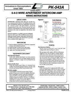
Transcription of PK-543 3-4-5 Wire Intercom Amplifier Wiring …
1 WIRINGS uite Stations - may be wired in risers as shown in the wiringlayout diagram, Fig. 1. Each riser requires one twisted pair,#22 (or as required for type of station) plus one conductor,#22 for each suite served by the riser. Maximum length is400 ft. (120 meters). Additional risers may be added asneeded. Cable should not be run in the same conduit with(or too close to) electrical Wiring , background music wiringor very close to fluorescent lights, dimmers or other electri-cal equipment. Leave sufficient cable in each box to makeconnections. Do not cut cable at each - Wiring should be 2 conductor, #18. Maximumcable length is 80 feet (24 meters), or up to 200 feet (60 meters)using #14 wire .
2 Route cable away from suite station Release - Wiring should be 2 conductor, #18 cable. Maxi-mum length is 50 feet (15 mtr). To use 24 volt door release, usea LEE DAN PS-30A transformer and connect as in Fig. - Before connecting, make certain wires are freefrom shorts or grounds. Make connections as shown inFig. 4, observing the following not apply power to transformer primary until entiresystem has been installed and all Wiring checked forshorts or grounds. The common wires connecting toterminals 1,2,3,E and 5 should show open circuit whentested with an twisted pair Wiring as shown. Do not interchangewires or reverse wire APARTMENT Intercom AMPWIRING INSTRUCTIONSFig.
3 1 Add Risersas required117 VACPS-30A TransformerEntryPanelDoorOpenerDoorOpene rTo Additional SuitesFor 3- wire stations:1 twisted pr #22, plus 1 cond.#22 gauge per suiteor,For 4- wire stations:1 twisted pr #22 and 1 cond.#22 common, plus 1cond. #22 gauge per suiteor,For 5- wire stations:2 twisted pr #22, plus1 cond. #22 per suiteTransformer81624 VAC#18 DKC24PK-5432 cond. #18 ZWFig. 3 OPTIONAL DIODE CONNECTIONFig. 2 OPTIONAL CONNECTION FOR 24 VACDOOR Amplifier may be installed inside entry panel whenusing BB-200 series housing. If necessary to install theamplifier elsewhere due to temperature extremes, etc., orbecause a small panel is being used, 2 conductor, shieldedcable must be used for the entrance panel speaker wiringand a 1 conductor shielded wire must be used for the Buzz wire (connect shield drain wire to Amplifier terminal G).
4 NOTE: PK-543 should be located at least three feet (1 meter)away from transformers or other electrical equipment andmust be kept away from direct heat or extreme Temp. 0-30 the PK-543 must be located away from the entrypanel, shielded cable must be used for terminals A, G,and Z (or ZW). Connect shield drain wire to amplifierterminal G. In addition, one of the following steps mustbe taken to prevent the possibility of Oscillation occur-ring at the Suite Stations and the Entry Panel Speakerwhen switching from Talk to ENTRANCE TONE switch must be set to the OFF 1N4003 diode must be placed in series with theZW terminal. The anode of the diode must beconnected to the ZW terminal.
5 Refer to Fig. the Z terminal is not being used for a secondsuite entrance, connect the 'BUZZ' wire to Zinstead of ZW. This will give a steady tone insteadof a warble the VOICE VOLUME level down until theOscillation Stations:Innovations in Communicationssince 1955TM PK-543IN-487 (5/01)800-231-1414 631-231-1414155 Adams Avenue Hauppauge, NY 11788-3699 Fax 631-231-1498 MAILBOXES DIRECTORIESANNUNCIATORS wire & CABLE NURSE-CALLWith continuous product improvement, specifications are subject to change without DAN COMMUNICATIONS, INC. Page 2 IN-487 (5/01)FINISH INSTALLATIONI nstall the Amplifier in one of three manners: 1) Insideoptional JB-200 junction box, 2) In remote location such asutility closet, basement, etc.
6 , 3) To rear of specificallydesigned LEE DAN entrance panel, in a position that willnot interfere with panel components. Install suite stations onhousings. Do NOT overtighten screws on plastic power transformer primary to 117 AND CHECKOUTAt entrance panel, push each button. Check to determine if thecorrect suite is buzzed each time. At each suite, push TALK andLISTEN buttons to communicate with someone at the entrancepanel; then push DOOR button to check door release VOICE VOLUME: is adjustable externally using a small screw-driver through the port hole on the front of the PK-543labeled VOICE VOLUME .2. PROGRAMMING SWITCHES:Switch # #1 DOOR DELAY: to enable door delay, switch to left.
7 Todisable door delay, switch to right. #2 SHORT DOOR TIME: with the door delay switch enabled, theshort door delay may be selected. With the second dipswitch to the left, the door delay will be approx. 16seconds. To the right, the delay is 8 seconds. #3 ENTRANCE TONE: call tone at entry panel is enabled withthe 3rd dip switch to the right, and disabled to the left. #4 Not Entire System Dead - Check 117 VAC at transformer primary, 16 VAC at transformer secondary,and Wiring to No Talk - Check Wiring to terminals1 and 2 shorted or open, and wiringto entrance panel speaker open orshorted. Suite station may be testedby No Listen - Check Wiring to termi-nals 1 and 3 shorted or open andshort between terminals 1 and No Door Operation - Check Wiring todoor release shorted or open, de-fective door release, and door but-ton on suite station.
8 Check wiringto terminals 2 and 3, or 1 and No Buzzing -Check Wiring toPK-543 terminal Z, or ZW, panelpush-buttons, and Wiring to suitestations terminal Excessive Hum or Distortion Checkwiring installed too close toelectrical Wiring or electricaldevices, PK-543 installed tooclose to transformers or electricaldevices, twisted pair Wiring notused as required, or PK-543volume set too Radio Interference - Checkconnection from the PK-543terminal G to electrical :This connection is notshown on Wiring diagram, sincethe situation is not alwaysimproved by adding it. Ifproblems persist, consult Oscillation - Check Wiring step 4 onpage 1. If oscillation persists, con-nect a model 15-MFD non-polarcapacitor across terminals A and Gon the PK-543 : Entrance Tone (if used) willbe lower with TONE VOLUME: is adjustable externally using a small screw-driver through the port hole on the front of the PK-543labeled TONE VOLUME.
9 NOTE: Adjust Tone Volume tomaximum only when using PK-502B multi-entrance BUZZ 1: ZW terminal is a warble tone BUZZ 2: Z terminal is a steady tone output. To be used for calltone at suite the system fails to operate properly, check Wiring . If Wiring iscorrect, check the following points: #22 wire UNLESS SHOWN THE ENTRANCE PANEL HAS A HANDSET, CONNECT ITIN PLACE OF THE DC DOOR OPERATION CONNECT DOOR RELEASETO L- (YELLOW) AND L+ (YELLOW/BLACK). , 4 AND 5 wire STATION TYPES MAY BE USED IN ANYCOMBINATION, BUT NOT USUALLY ON THE SAME CABLERUN.