Transcription of POINT I/O Modules - literature.rockwellautomation.com
1 POINT I/O Modules Bulletin 1734. Selection Guide Important User Information Solid state equipment has operational characteristics differing from those of electromechanical equipment. Safety Guidelines for the Application, Installation and Maintenance of Solid State Controls (publication available from your local Rockwell Automation sales office or online at ) describes some important differences between solid state equipment and hard-wired electromechanical devices. Because of this difference, and also because of the wide variety of uses for solid state equipment, all persons responsible for applying this equipment must satisfy themselves that each intended application of this equipment is acceptable. In no event will Rockwell Automation, Inc. be responsible or liable for indirect or consequential damages resulting from the use or application of this equipment.
2 The examples and diagrams in this manual are included solely for illustrative purposes. Because of the many variables and requirements associated with any particular installation, Rockwell Automation, Inc. cannot assume responsibility or liability for actual use based on the examples and diagrams. No patent liability is assumed by Rockwell Automation, Inc. with respect to use of information, circuits, equipment, or software described in this manual. Reproduction of the contents of this manual, in whole or in part, without written permission of Rockwell Automation, Inc., is prohibited. Throughout this manual, when necessary, we use notes to make you aware of safety considerations. WARNING. Identifies information about practices or circumstances that can cause an explosion in a hazardous environment, which may lead to personal injury or death, property damage, or economic loss.
3 IMPORTANT Identifies information that is critical for successful application and understanding of the product. ATTENTION. Identifies information about practices or circumstances that can lead to: personal injury or death, property damage, or economic loss. Attentions help you identify a hazard, avoid a hazard, and recognize the consequence. SHOCK HAZARD. Labels may be on or inside the equipment, such as a drive or motor, to alert people that dangerous voltage may be present. BURN HAZARD. Labels may be on or inside the equipment, such as a drive or motor, to alert people that surfaces may reach dangerous temperatures. Allen-Bradley, Rockwell Automation, POINT I/O, POINT Guard I/O, POINTBus, GuardLogix, , RSLogix 5000, DeviceLogix, and TechConnect are trademarks of Rockwell Automation, Inc. Trademarks not belonging to Rockwell Automation are property of their respective companies.
4 Table of Contents Chapter 1. POINT I/O Family Overview.. 5. The POINT I/O System .. 6. POINT I/O Features .. 7. Specify a POINT I/O System .. 8. Chapter 2. Select POINT I/O Communication Overview.. 9. Interfaces NetLinx Open Network Architecture.. 9. Select a Network .. 10. EtherNet I/P Network .. 11. ControlNet Network .. 12. Memory Requirements .. 14. DeviceNet Network .. 15. PROFIBUS DP Network .. 17. Communication Adapter Environmental Specifications .. 18. Chapter 3. Select POINT I/O Modules Select POINT I/O Modules .. 19. Digital I/O Modules .. 20. Digital AC Input Modules .. 21. Digital AC Output Modules .. 21. Digital DC Input Modules .. 22. Digital DC Output Modules .. 22. Digital Contact Modules .. 23. Digital I/O Modules Environmental Specifications .. 24. Self-Configurable Modules .. 24. Self-Configurable Modules Environmental Specifications.
5 25. Analog and Temperature I/O Modules .. 26. Analog Input Modules .. 27. Temperature Input Modules .. 28. Analog Output Modules .. 31. Analog and Temperature I/O Modules Environmental Specifications .. 32. Specialty I/O Modules .. 32. 1734-232 ASC and 1734-485 ASC Serial Interface Modules .. 32. 1734-SSI Synchronous Serial Interface Module with Absolute Encoder .. 33. 1734-ARM Address Reserve Module .. 35. 1734-CTM Common Terminal and 1734-VTM Voltage Terminal Modules .. 35. 1734-4 IOL 4 Channel IO-Link Master Module.. 36. Specialty I/O Modules Environmental Specifications.. 37. Counter Modules .. 38. Counter Modules Environmental Specifications .. 41. Safety I/O Modules .. 41. POINT I/O Accessories .. 48. iiiPublication 1734-SG001F-EN-P - September 2015. iv Table of Contents Chapter 4. Select a Terminal Base Assembly Terminal Base Assembly.
6 51. One-piece Terminal Bases.. 53. Chapter 5. Select a Power Supply Unit POINT I/O Communication Adapters .. 55. Expansion Power Supplies .. 56. Field Power Distributor.. 59. Chapter 6. Mounting Requirements Power Supply Distance Rating .. 63. Mount the POINT I/O System .. 64. Approximate Mounting Dimensions .. 65. Chapter 7. Related Documentation Publication 1734-SG001F-EN-P - September 2015. Chapter 1. POINT I/O Family Overview The POINT I/O family has modular I/O Modules that are ideal for applications where flexibility and low-cost of ownership are key for successful control system design and operation. As a key element in the Rockwell Automation Integrated Architecture, its comprehensive diagnostics and configurable features allow the product to be easily applied to any automation system and reduce engineering costs through standardization.
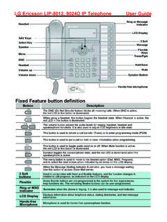
7 It can be used in remote device panels, local control panels, and can be accessed from many locations including the Internet. This product has just-what-you-need granularity in 1 to 8 points to reduce system cost and size. Available features include Channel Level Diagnostics for quick troubleshooting, multiple termination options and flexibility to save money, cabinet space and commissioning/troubleshooting time, the ability to mix/match Safety I/O on the same bus, and available DeviceLogix for local control, fast response time. Self-Configuring Modules are also available to reduce/simplify your design and your inventory. 5 Publication 1734-SG001F-EN-P - September 2015. 6 POINT I/O Family The POINT I/O System B B. A A. C. 45215 45216. 1734-TOP or 1734-TOPS. One-piece Terminal Base with Screw or Spring Clamp The base (A) mounts onto the DIN rail and provides the backplane.
8 The POINT I/O module (B) snaps into the base. The removable terminal block (C) also snaps into the base and provides the wiring and terminations for field-side connections, as well as system power for the backplane. POINT I/O has 4 major components: I/O Modules provide the field interface and system-interface circuitry Communication interface Modules provide the network-interface circuitry Terminal base units provide the wiring and signal termination for field-side connections and system power for the backplane Power distribution Modules provide the expandability of the POINT . I/O system and the flexibility to mix a variety of signal types 1734 POINT I/O Modules offer 1 to 8 points per module. The I/O Modules are interfaced to a network through a communication interface, which includes a built-in power supply that converts incoming 24V DC power to 5V DC.
9 Backplane power. Each type of communication interface (Network Adaptor). supports a maximum of 13 to 17 I/O Modules , with a maximum of 10 A field power. The I/O Modules receive power from the power supply through the backplane. With an external power supply, you can expand a POINT I/O. assembly up to a maximum of 63 I/O Modules or 504 channels. Publication 1734-SG001F-EN-P - September 2015. POINT I/O Family 7. POINT I/O Features Adapters ControlNet DeviceNet EtherNet I/P. Profibus I/O Types Digital Analog AC/DC. Thermocouple RTD. Specialty Module Density 1 8 points Specialty Modules Encoder 1 MHz Counter In Counter In with Outputs Serial RS232. RS485. RS422. Channel Isolated Thermocouple RTD. Serial Synchronous Interface (SSI). Address Reserve 4 Channel IO-Link Master Module Features Channel-level diagnostics (LED indicator and electronic).
10 Channel-level alarm and annunciation (electronic). Channel-level open-wire detection with electronic feedback Channel-level short-circuit detection with electronic feedback Parameter-level explicit messaging Removal and insertion under power (RIUP). Horizontal or vertical mounting without derating Automatic Device Replacement Add-On-Profiles in RSLogix 5000. Network DeviceNet (including SubNet connectivity). Connectivity ControlNet (Logix controller only). EtherNet/IP (Logix controller only). PROFIBUS DP. OPC/DDE Data Monitoring . Environmental Class I, Division 2/Zone 2, Marine Certification, European ATEX Zone Style 2 3G. Modules per Node, Up to 63. max Publication 1734-SG001F-EN-P - September 2015. 8 POINT I/O Family Specify a POINT I/O System Follow these steps as you specify your POINT I/O system: Step Remember to select 1 Select a communication the appropriate interface module interface a communication interface that Choose the interface module for your meets the power requirements of operating system.