Transcription of POLES ROUND, STRAIGHT, AND TAPERED - Techlight
1 : 20180530-R1 WARNING: ALWAYS INSTALL FIXTURES ACCORDING TO NATIONAL ELECTRICAL CODE (NEC) AND LOCAL CODES. FAILURE TO DO SO WILL VOID THE WAR-RANTY AND COULD CAUSE DAMAGE TO THE FIXTURE OR MAY RESULT IN PERSONAL : TURN ELECTRICITY OFF AT THE CIRCUIT BREAKER BEFORE INSTALLING OR PERFORMING MAINTENANCE ON information deals with structures supplied by Techlight along with certain safety issues. It is NOT a comprehensive description of how to install these structures. Installation contractors must be relied upon for equipment and practices that meet the conditions of each job cannot be responsible for any damage that may occur during or after installation, or for any structure that has been modified by the purchaser or that is used in some way other than our application recommendations. INSTALLATIONSHIPMENT - The Bill of Lading should be checked carefully to verify a complete delivery of all required material. Quantities of all material including boxes, cartons, crates, pallets, and POLES should be verified.
2 Shipment shortages and damages should be communicated immediately to the factory and must be clearly noted on the Bill of Lading by the person in charge of receiving the shipment; this will protect your right to file a claim. Techlight is not responsible for filing the claim or contacting the carrier on the behalf of the customer. All quantities as well as the condition of all material must be verified and noted on the Bill of Lading, including possible concealed damage. Failure to follow these instructions will may void any rights to file a - During unloading, only qualified personnel and equipment should be used. Forklifts and cranes are most commonly used for unloading and handling POLES and related materials. When unloading with a crane, only use nylon straps to prevent damage to the POLES surface and finish. When using a forklift for unloading and moving POLES , either lift from the sides or use the spear technique. When side lifting insure that the forks do not come into contact with the pole surface otherwise the pole surface or finish will be damaged.
3 When lifting a pole by the spear method, only do so from the base end of the pole ensuring that the hand hole frame and ground lug are not damaaged as both are approximately 18 from the base plate. Also be careful not to damage the pole walls as this can be visible from the outside surface and can reduce the structural integrity of the pole. The spear method should only be done by experienced and qualified operators. STORAGE - POLES which need to be stored prior to installation must be protected from moisture. All packing material should be removed prior to storage (see warning label attached to the POLES ). Adequate space between the ground and the POLES is required to ensure safe storage. It is recommended that a minimum of 6 be maintained between the ground and POLES during storage. Pole placed in direct contact with the ground presents a high risk of surface finish violation which will lead to the deterioration of the finish and void the warranty.
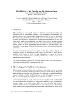
4 It is also recommended that the supporting blocking (dunage) used to elevate the POLES from the ground be made of wood, padded with foam or other padded material to ensure that the finish in not damaged during placement and storage. POLES stored on a hard surface will create impact damage to the finish and void the warranty. Excessive moisture will also attack the finish and void the warranty so the stored POLES should not be subjects to prolonged moisture or water. The pole should be supported in multiple locations as level as possible and should be supported with no larger spacing than 10 to prevent the POLES from bowing while stored. (FIGURE 1)I NNOVA T ION IN IL L UMINA T I ONI NNOVA T ION IN IL L UMINA T I ONI NNOVA T ION IN IL L UMINA T I ONI NNOVA T ION IN IL L UMINA T I ONINSTALLATION INSTRUCTIONSPOLES ROUND, straight , AND TAPEREDFIGURE 1 FIGURE 2(EXAMPLE OF STORED POLE WITH PROPER SUPPORT)10 Max10 MaxANCHOR BASE FOUNDATION - The following written procedure is provided as a general guideline.
5 It is recommended that foundation contractors with specific knowledge, familiarity, and experience be used when constructing these foundations. Work should not be performed until the appropriate design approval has been received and all necessary materials have been delivered and inspected. Local building codes must also be considered prior to installation as prevailing wind and soil conditions must be - Paper templates are provided for each type of base configuration. The templates are marked for the specific job and are shipped with the anchor bolts. Anchor bolts and templates can be shipped with the POLES or shipped early to allow for pier construction prior to the pole delivery. The paper template is typically used to transfer the correct hole pattern to a piece of plywood or steel sheet. The template is then used to ensure the anchor bolts are located in the correct location prior to the concrete setting (FIGURE 2) up. Note: Rigid templates can also be purchased, please contact your sales person for availabilty and cost.
6 SETTING THE ANCHOR BOLTS - To set the anchor bolts, first align the template over the center of the foundation, typically resting on the top of the Sono-tube of form. Thread one nut onto each of the anchor bolts to allow the proper bolt projection above the concrete to accommodate the base plate, two flat washers, a leveling nut and top nut plus additional length for adjustment leveling (typically +/-). Insert one anchor bolt into the template and push it into the concrete until the nut rests on the template. The hook on the anchor bolt can be facing any direction, but the preferable orientation is to point the hook outward, leaving at least 3 of concrete between the end of the hook and the edge of the augured hole or concrete. Care should be taken to ensure that the anchor bolts are set in the concrete plumb. Repeat this procedure for all of the remaining anchor bolts. Once all the anchor bolts are set and plumb, the concrete must be vibrated to ensure a strong bond exists between the concrete and the anchor bolts.
7 The concrete must be allowed to cure to its full compressive strength before any loads can be applied. (FIGURE 3)FIGURE : 20180530-R1 SETTING THE ANCHOR BOLTS continued - When the foundation or pier has cured, the anchor bolts should protrude from the concrete in a vertical (90 ) orientation from the top of the footing. Bolts should be equally spaced from one another and from the center point of the pier or footing. The anchor bolt pattern should easily accommodate the base plate of the pole structure. (FIGURE 4)LEVELING - One leveling (the bottom) nut and one top (hold down) nut should be utilized per anchor bolt. One flat washer per leveling (bottom) nut and one per top (hold down) nut should also be utilized per anchor bolt. Space between the foundation and the base plate is required for ventilation. The base plate should never set directly on the foundation this will induce corrosion, void the warranty, and components in the concrete will attack the pole and finish.
8 It should never be presumed that the pole base is level with the pole or flat. All POLES should be leveled by use of a level to the opposing sides of the pole while reaching as high as possible. When leveling TAPERED POLES you should take readings from both side of the POLES and split the difference. (FIGURE 5)GROUT-NOT RECOMMENDED - Techlight does not recommend grouting to seal the pole base to the foundation. Grouting does not allow for proper moisture drainage from the pole interior. Grouted POLES have a tendency to hold water which causes internal corrosion. If grouting is to be installed, use the following guideline: Place a non-shrinking or expanding type concrete grout in the void between the base of the pole and concrete foundation. Puddle the grout around the edge of the pole base and firmly pack the space between the pole and the foundation. The pole base must be thoroughly vented with applicable weep/draining outlet tubes. Use a short piece of small-diameter pipe to make a drain hole through the grout to the pole interior.
9 Where possible, the tube should slope to the exterior of the base plate to induce drainage. Failure to weep the base plate will cause premature corrosion voiding the warranty and may possibly cause the pole to fail. (FIGURE 6)VIBRATION & FATIGUE (HARMONICS) - Although very rare, vibrations severe enough to cause damage can occasionally occur in any type of pole structure. The conditions that induce vibration are a randomly occurring phenomenon caused by a constant low wind. This unpredictable course of nature requires structures to be inspected weekly for the first three months of operation. It is imperative to communicate any pole vibration to the factory immediately. Keep in mind that pole structures will sway in the wind. There is a difference between vibrations ( harmonic) and pole sway. There are basically two types of vibration, typically the vibration will occur at the top of the pole however a second type of vibration can occur in the middle of the first type of vibration or harmonics is the hardest to detect as this movement is at the top of the pole and can be confused with pole sway.
10 Harmonic vibration is a cycle that repeats its self such as a back and forth movement that is the exact same distance and direction from the center of the pole without variation in the movement for an extended period of time. Any movement that does not repeat itself in an opposing direction is pole sway. The second type of vibration is detected when the middle of the pole moves side to side and the top and bottom of the pole remain stationary, this is also referred to as a hula-dance type motion. Both types of harmonics will damage the pole and void the warranty, prolonged harmonics will cause structural failure of the vibrations most commonly occur when the pole is stood without the fixture and/or arms being installed. Harmonics are more likely to happen with a square straight pole rather than a round pole, and are even less likely to occur in TAPERED POLES . Regardless of the of the type, size, and height of the pole, harmonics can occur as random acts and are unpredictable ARM MOUNTS FOR ROUND AND ROUND TAPERED POLES Because the fixture heads and arms are installed onto the pole prior to it being stood up, extra care must be taken to ensure the arms are installed square to the pole.