Transcription of PolyBlend Dry Polymer Feed System Model DP2000
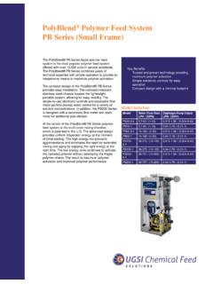
1 PolyBlend Dry Polymer feed SystemModel DP2000 The PolyBlend DP2000 System is a reliable drypolymer feed System for use in water and wastewaterapplications. The DP2000 is an integrated equipmentpackage capable of automatically preparing ahomogeneous Polymer DP2000 consists of the DD4 dry polymerdisperser, and two stainless steel mix tanks, operatingin an alternate DP2000 is speci cally designed to provideuniform mixing. Dry Polymer and water are initiallymixed in the DD4 Polymer disperser exposing thesolution to a high shear agitation via mechanicalmixing.
2 The high shear agitation ensures properactivation of the Polymer and prevents unwantedagglomerations. After brief exposure, the solutionexits the high shear mixer and ows into the second stage mix is a longer, low shear mix. Therotating impeller in the secondary mix tank is a hollow-wing design and covers over halfthe width of the tank. The low shear mixingcontinuously and uniformly moves the solutionvertically and horizontally resulting in noagglomerations or broken Polymer a low level is sensed in one of the mix tanks, athree-way valve directs ow to the empty tank andthe empty tank discharge valve closes simultaneouslyto isolate the empty tank from the Polymer DD4 disperser begins a make down sequenceand lls the empty tank.
3 After the tank ll and mixingsequence is complete and the alternate tank reacheslow level, the full tank discharge valve is opened and ow is directed to the Polymer solution feed three-way valve then directs ow to the emptytank, the discharge valve on the empty tank closesand the sequence Benefits Reliable performance Field proven Reduced Polymer consumption Fully automated operation Operator interface controls Improved safety featuresThe DP2000 is controlled through an easy-to-usemicroprocessor-based operator interface.
4 The LCDdisplay enables complete operation of all functionsincluding component status, timers, counters, cationsElectrical480 VAC/ 50-60 Hz/ 3 Ph575 VAC/ 50-60 Hz/ 3 PhWater LPM (30 GPM)Tank L (750 USG)* Polymer FeedUp to kg (31 lbs)/hr dry poly-mer based on a solutionControl PanelNEMA 4X PLC basedOptionsSee back*Note: Consult UGSI Chemical feed , Inc. with regardsto dosing amount and your LayoutTop ViewFront ViewAvailable Options Diaphragm metering pump Progressive cavity metering pump Batch tanks / single or tandem Integral compressor m3( ft3) hopper m3(20 ft3)
5 Hopper Bulk bag frame Bulk bag frame with hoist Bag dump hopper Low powder level indication Supply water pressure reducing valve Final feed pumps Final feed post dilution Large hold tanks Transfer Chemical feed , West Garden RoadVineland, NJ 08360 Toll Free: 855-669-3845 Local: 856-896-2160 Fax: 856-457-5920 Email: 2014 UGSI Chemical feed , to change without prior No. is a trademark of UGSI Chemical feed , information provided in this literature contains merely general descriptions orcharacteristics of performance which in actual case of use do not always apply asdescribed or which may change as a result of further development of the products.
6 Anobligation to provide the respective characteristics shall only exist if expressly agreedin the terms of a written Tank, L (750 USG)2 Speed Reducer, Worm Gear, 30:13 Motor-Tank Mixer, , 1725 RPM, TEFC4 Impeller Mix Tank, 60 RPM5 Tank Discharge, (3 ) NPT6 Fork Truck Cutout7 Sight Tube, Level Indication8 System Control Panel9 Solution Inlet, Back ow Drain, (1/2 ) NPT10 Bulk Bag Frame11 Hoist Motor/Trolley12 Bag Holder13 Mono Rail14 Structure Cable15 Hopper w/Collar16 Powder Feeder17 Junction Box, Interconnections18 Air Compressor w/Tank19 Solution Discharge, Wetting Device, ) (1-1/2 )
7 NPT20 Condensate Drain21 Pressure Gauge, Compressed Air22 Pressure Gauge Supply Water23 Pressure Gauge Differential Water24 Motor Impeller, HP, 3450 RPM25 Pump, (Diaphragm)26 Wetting Impeller Housing27 Pneumatic Cylinder, Isolation Plunger Actuator28 Wetting Bowl29 Emulsion Polymer Inlet, (1/2 ) NPT (Optional)30 Supply Water Inlet, (1-1/2 ) NPT31 Shutoff Valve, (Manual)32 Valve, Pneumatic Ball, Supply Water33 Level Control, Switch Assembly34 Tank Drain, (3 ) (F) NPT, (Capped)35 Flow Control Valve, Water Supply