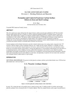
Transcription of Porosity Defects in Iron Other methods for …
1 AFS Transactions839 Silver Anniversary Paper, Div. 5 Porosity Defects in IronCastings From Mold-MetalInterface NaroASI International, , OhioABSTRACTIn the 25 years since the original paper was written, there havebeen considerable technical advances in foundry binder tech-nology, as well as sand mixing and processing equipment. Thetechniques and equipment available to the foundrymen in 1974were rather primitive, compared to today s improved binderchemistry and selection, mixing and binder metering equipmentand sand reclamation paper updates the original 1974 research on porositysusceptibility of gray and ductile iron castings, prepared withcores bonded with the, then, newly developed urethane types ofnobake binders.
2 The 1974 study was aimed at delineating theeffects of core- and moldmaking variables on Porosity suscepti-bility and developing remedial practices to eliminate binder-related Defects when they occur. Also investigated were theeffects of casting variables and how they relate to the occur-rence of such updated research focused on the evaluation of currentresin technology, iron oxide additions, and the effects of poros-ity inhibiting ferroalloys. Lastly, Other unpublished research bythe author during the ensuing 25 years is also and improved binder formulations of 1998 provided virtuallyidentical casting results compared to the 1974 research. Binder ratiosof polyol resin to polyisocyanate component less than one (favoringhigher levels of the polyisocyanate component) tended to increaseoverall Porosity susceptibility.
3 Balanced or ratios greater than onewere, in general, not susceptible to defect formation. Defect forma-tion was enhanced by high pouring temperatures, especially whenpolyol to polyisocyanate ratios were less than one, and when highbinder levels were binder dispersion from sand mixing was also responsible forincreasing the overall susceptibility to these types of Defects . Poros-ity Defects resulting from use of unfavorable binder and/or castingpractices could be eliminated by adding relatively small additions ofred iron oxide (hematite or Fe2O3) to the sand mix. The use ofmagnetite or black (Fe3O4) grades of iron oxide were not nearly aseffective in preventing addition of nitrogen-stabilizing elements, such as titaniumand zirconium, were effective, to varying degrees, in eliminatingporosity.
4 Best results were obtained with additions of proprietary Ti-bearing gray iron inoculants. Addition of proprietary ferrosilicon-based inoculant alloys containing either Ti or Zr were also very99-206effective in eliminating Porosity . Additions of Zr silicide to a new,proprietary oxy-sulfide-containing inoculant was also very effectivein eliminating methods for eliminating Defects , although not nearly aspractical, were core post-baking at 450F (232C) and use of corecoatings modified with red iron and subsurface gas Defects have always been common andtroublesome Defects in gray iron and Other castings poured in greensand molds. Within the past 30 years, however, innovations insynthetic binder technology have resulted in movement away fromgreen sand molding and toward total nobake molding and coremakingprocesses and the accompanying new types of casting growth in phenolic urethane binder technology since 1970,the year phenolic urethane nobake (PUNB) binders were introduced,has been phenomenal (Fig.)
5 1). When the original Porosity paper waswritten in 1974, only million lb of phenolic urethane binderswere consumed by the foundry industry. In 1998, it is estimatedthat 129 million lb of these resins (3079 truckloads, a truckloadweighing 42,000 lb) were consumed in the United States. Estimatedworldwide use is generally considered to be over 300 million a result of the increased acceptance and consumption of phenolicurethane binders, occurrences of binder-related gas Defects have, attimes, become very troublesome in foundries using these speaking, there are three major sources that maycontribute to Porosity formation in gray iron castings. These are:1) high initial gas content of the melt, originating from either thecharge ingredients, melting practice or atmospheric humidity;2) reaction of carbon and dissolved oxygen under certain meltconditions;3) mold-metal reactions between evolved mold and core gases atthe solidifying casting 16In addition, any combination of these three sources may have acumulative effect on promoting Porosity formation.
6 However, thegases normally held responsible for subsurface Porosity Defects arenitrogen and is a definite distinction between Porosity Defects andblows. Porosity Defects are chemical in nature, and result when liquidmetal becomes supersaturated with dissolved gases during meltingor pouring. The ensuing discontinuities are present as discrete voidsthat may be rounded or irregularly shaped in the solidified casting,and generally lie just under the casting surface. Conversely, blows orFig. 1. Phenolic urethane resin consumption in the United Transactionsblowholes are a physical or mechanical problem related to theinability of decomposed core and mold gases to escape from the moldcavity, either through permeability or appearance of the subsurface Porosity Defects resulting fromthe preceding sources may take numerous shapes but usually form aseither small, spherical holes (sometimes elongated or pear-shaped),called pinholes, or larger, irregularly rounded holes or irregularlyshaped fissure type ,8,13,15,16 The internal surfaces of theresultant holes may be 1) oxidized, 2) lined with a shiny graphite filmor 3)
7 Contain slag or manganese sulfide ,5,8 Although the technical literature contains a large amount of workdescribing Porosity Defects and the metallurgical practices thatpromote the occurrence and treatment of such Defects , relatively littleexperimental work had been conducted in the area of chemical binderinduced mold-metal interface Porosity reactions. Investigations thathave been conducted in this area have generally been limited todiscussions of potential problems existing when using high N (urea)furans, and to a lesser extent, shell and oil-alkyd-isocyanate 1974, minimal research had been conducted in determininghow various core and moldmaking parameters affect the incidence ofporosity Defects with chemical binder systems.
8 This lack of researchhas continued during the ensuing 25 BINDER SYSTEMSThe phenolic urethane resin system consists of nobake and gas-curedresins; both systems consist of two resin components. Part I is aphenolic resin (poly-benzylic-ether-phenolic resin) diluted approxi-mately 50% by solvents. Part II is a polymeric di-isocyanate resindiluted with approximately 25% solvents. The solvent can be eitheraliphatic or aromatic in primary purpose of the solvents is to reduce binder , the viscosities of the Part I and Part II resins are adjustedto 200 cps (centipoise) or lower, to provide good pumpability, rapidand efficient sand coating qualities and good flowability of mixedsand. A second purpose of the solvents is to enhance resin amine-based catalyst is used as the curing agent for the nobakebinder, while a gaseous amine (triethylamine or dimethylethyl amine)is used for the gas-cured the general chemistry of phenolic urethane bindersremains essentially the same as the system investigated in 1974, therehave been numerous changes in current resin formulations involvingthe solvent system, as well as base phenolic resin system.
9 The Part Iphenolic resin has been modified to reduce odor by reduction in thelevel of free formaldehyde. This becomes especially apparent whenhot foundry sands are used. In addition, because of efforts to reducesolvent evaporation into the atmosphere, the solvent system has beenmodified extensively to incorporate higher boiling point solvents ornew solvent systems with improved environmental organic-based systems, the phenolic urethane family ofbinders is composed of only four basic elements: carbon, hydrogen, nitrogen and phenolic urethane systems, the N component is associatedsolely with the polyphenyl polyisocyanate (Part II) binder compo-nent. Part I, or the hydroxyl-containing phenolic binder component,contains no nitrogen.
10 Elements of concern to the foundryman needbe limited to only N and H; carbon and oxygen from the binderusually present no problem because the high silicon content of grayiron acts to suppress the formation of carbon monoxide comparison purposes, H and N contents of Other popular resinbinder systems are:NitrogenHydrogen*H2 ONobake N2 N2 * Associated with organic of these elements, including moisture, may react or combinein numerous ways to provide the necessary conditions that favorporosity formation. The following gaseous reactions are thermody-namically possible and, under the right conditions, may occur at themold-metal interface:Binder H (nascent) H2 (g)Binder N (nascent) N2 (g)Fe + H2O vapor (binder) FeO + 2H (nascent)3 H2 (binder ) + N2 (binder) > 2NH3 (g) 6H (nascent)+ 2N (nascent)FeO + C (binder) CO (g) + FeWhile the first four reactions are likely to provide both surfaceand subsurface Porosity Defects , the last reaction usually results onlyin surface Defects , such as pockmarking or, more frequently, lustrouscarbon laps and surface an organic binder thermally degrades, H and N are liber-ated in the nascent or atomic form.