Transcription of Positioner with HART Communication Type 3780
1 The microprocessor-controlled Positioner ensures a preset as-signment of the valve stem position to the electric input signal. Itcompares the 4 to 20 mA reference input signal received fromthe control device to the travel of the control valve and generatesthe corresponding pneumatic output signal pressure (outputvariable). Suitable for attachment to both linear and rotary actuatorsThe Type 3780 Positioner is equipped with an interface whichcomplies with the HART Field Communication Protocol, enab-ling connection to a PC or HART -compatible handheld communi-cator (configurator) for bidirectional data s TROVIS-VIEW software and the device-specificdatabase module can be used to configure and parameterizethe Positioner .
2 The Positioner can, however, also be operatedwith other suitable software with type of protection "Intrinsic safety EEx ia IIC T6","EEx n" for Zone 2 or in combination with Type 3770 FieldBarrier with type of protection "Flameproof enclosure EEx d"The digital data processing feature offers the following advant-ages over conventional positioners: Automatic adjustment of zero and span when initializing thepositioner Automatic detection of errors in the actuator or pneumaticsystem Operating direction selectable using software functions,therefore independent of the mounting position Selectable characteristics Simple modification of control parameters even during oper-ation Monitoring and diagnosis functions, self-test functions forfault alarm output, software limit switches and position trans-mitters.
3 Total valve travel (travel integral) Supports advanced valve diagnosis using samson sTROVIS-EXPERT software Continuous monitoring and adjustment of zero Minimum air consumption Permanent storage of all parameters in the EEPROM Optionally available with forced fail-safe venting action tovent the actuator via the 2/2-way valve (Fig. 4, item 4) uponfailure of the external signal. As a result, the control valve isforced to move to its fail-safe position. This function can beactivated using a hardware with HART CommunicationType 3780 ApplicationSingle-acting or double-acting Positioner for attachment topneumatic control valves.
4 Supplied with a standardized electricinput signal from 4 to 20 mA For rated travels from 5 to255 mm and opening angles up to 120 Smart instrument according to the HART Field CommunicationProtocol. Designed for types of protection EEx ia, EEx n or EEx Information SheetT 8350 ENEdition July 2003 Data SheetT 8380 ENFig. 1 Type 3780 Positioner with HART CommunicationFig. 3 Type 3780 Positioner with opened caseWrite protection switchFig. 2 Ex d Positioner with Type 3770 Field Barrier Principle of operation The travel of the final control element is detected using thenon-contact inductive displacement sensor (1) and transmittedto the microcontroller (2) via a converter.
5 In the microcontroller,the travel is compared to the set point, and the two pneumatic2/2-way switching valves (3, 4) are activated whenever adeviation ( error) occurs. Depending on the error, thesevalves either add air to (3) or vent air from (4) the pneumaticactuator using corresponding second microcontroller (5) manages the Communication ac-cording to the HART Field Communication Protocol. The fre-quency shift keying (FSK) signal used for Communication issuperimposed on the standardized electric current TROVIS-VIEW software package can be used to adjust andselect all required parameters and download these to the posi-tioner.
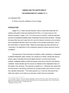
6 After that, the Positioner can operate independently ofthe PC or handheld default, the Positioner is equipped with a fault alarm outputused to signalize various errors and other relevant write protection switch located on the inside of the coverprevents that saved configuration data are overwritten to extend the function range of the Positioner include: Two inductive limit switches (proximity switches) or two soft-ware limit switches (to be configured via the program) One analog position transmitter which, independently of thereference input signal, converts the valve stem position intoan analog output signal (operating direction can be con-figured via the software)FSK2T 8380 EN25134 Fig.
7 5 TROVIS-VIEW Configuration and Operator Interface,dialog box for user-defined characteristic1 Inductive displace-ment sensor2 Microcontroller32/2-way valve42/2-way valve5 MicrocontrollerFSKF requency shiftkeying signal forcommunicationFig. 4 Functional diagram of Type 3780 Positioner 3T 8380 ENTable 1 Technical DataTravelDirect attachment to Type 3277:Attachment acc. to IEC 60534-6 (NAMUR):Adjustable 5 to 30 mm 5 to 255 mm or 30 to 120 with rotary actuatorsReference input signal wMinimum currentLoad impedanceSignal range: 4 to 20 mA, span: 4 to 16 mA Static destruction limit: 500 mA V (corresponds to 540 at 20 mA)Supply to 6 bar (20 to 90 psi)Output signal pressure0 bar up to capacity of supply air pressureCharacteristicAdjustable: linear/equal percentage/reverse equal percentage/freely programmableDeviation from characteristic 1 %Dead bandAdjustable from to 10 %, default.
8 %Resolution %Transit time240 s separately adjustable for exhaust and supply air Operating directionReversible, selection via softwareAir consumptionIndependent of supply air < 90 ln/hAir output capacityAdd air to actuator At p = 6 bar: mn3/h, at p = bar: mn3/h Vent air from actuator At p = 6 bar: mn3/h, at p = bar: mn3/h Permissible ambient temperature 20 to 80 C 40 to 80 C with metal cable glandFor devices equipped with position feedback indication only 20 to 80 C The values of the EC type examination certificate specified in Table 3 additionally apply to Ex influence %/10 KSupply influenceNoneEffect of vibrationNone up to 250 Hz and 4 gExplosion protectionEEx ia IIC T6 (see Table 3) or EEx nA II T6 Degree of protectionIP 54, (IP 65 special version)
9 Electromagnetic compatibilityRequirements met according to EN 50 081/50 082 and NAMUR Recommendation 21 Electrical connection1 plastic cable gland , blackSecond additional tapped hole kgFault alarm outputFor connection to signal converter according to EN 60 947-5-6 Static destruction limit: 16 VCommunicationHardware and software requirementsTROVIS-VIEW Configuration and Operator Interface (see Data Sheet T 6661 EN) Handheldcommunicator, Type 275 by Fisher Rosemount DTM acc. to Specification Integrationof other user interfaces possibleData transmissionHART Field Communication ProtocolImpedance in HART frequency range: receive 350 to 450 , send approx.
10 115 Software functionsAutomatic start-up; adjustment of characteristic, operating direction, reference input signalrange and transit time; limitation of the travel range; cross-over correction; automatic zerocorrection; fault alarms; total valve travel (travel integral); diagnosis messages; deviceinformation; non-volatile storage of data; test functions; logging via IBISF orced fail-safe venting actionInputKv valueTo be activated via internal switch6 to 24 V dc Ri approx. 6 K at 24 V dc (voltage-dependent)Switching point for 1-signal at values 3 V Switching point for 0-signal only at 0 limit switchesFor connection to signal converter according to EN 60 947-5-6, two Type SJ2-SN inductiveproximity switchesSoftware limit switchesFor connection to signal converter according to EN 60 947-5-6, two configurable limit values Hysteresis.