Transcription of POWER DIVIDERS AND DIRECTIONAL COUPLERS
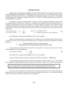
1 Transmitted PortCoupled PortInput PortIsolated Port1423P1P3PP248/4 Couplingfactor(dB)'& 1. DIRECTIONAL coupler POWER DIVIDERS AND DIRECTIONAL COUPLERSA DIRECTIONAL coupler is a passive device whichcouples part of the transmission POWER by a known amountout through another port, often by using two transmissionlines set close enough together such that energy passingthrough one is coupled to the other. As shown in Figure 1, thedevice has four ports: input, transmitted, coupled, andisolated. The term "main line" refers to the section betweenports 1 and 2. On some DIRECTIONAL COUPLERS , the main line isdesigned for high POWER operation (large connectors), while the coupled port may use a small SMA connector. Often theisolated port is terminated with an internal or external matched load (typically 50 ohms).
2 It should be pointed out that sincethe DIRECTIONAL coupler is a linear device, the notations on Figure 1 are arbitrary. Any port can be the input, (as in Figure3) which will result in the directly connected port being the transmitted port, adjacent port being the coupled port, and thediagonal port being the isolated port. Physical considerations such as internal load on the isolated port will limit port operation. The coupled output fromthe DIRECTIONAL coupler can be used to obtain the information ( , frequency and POWER level) on the signal withoutinterrupting the main POWER flow in the system (except for a POWER reduction - see Figure 2). When the POWER coupled outto port three is half the input POWER ( 3 dB below the input POWER level), the POWER on the main transmission line is also3 dB below the input POWER and equals the coupled POWER .
3 Such a coupler is referred to as a 90 degree hybrid, hybrid, or3 dB coupler . The frequency range for coaxial COUPLERS specified by manufacturers is that of the coupling arm. The mainarm response is much wider ( if the spec is 2-4 GHz, the main arm could operate at 1 or 5 GHz - see Figure 3). Howeverit should be recognized that the coupled response is periodic with frequency. For example, a 8/4 coupled line coupler willhave responses at n8/4 where n is an odd properties desired for all DIRECTIONAL COUPLERS are wide operational bandwidth, high directivity, and a goodimpedance match at all ports when the other ports are terminated in matched loads. These performance characteristics ofhybrid or non-hybrid DIRECTIONAL COUPLERS are self-explanatory. Some other general characteristics will be discussed FACTORThe coupling factor is defined as: where P is the input POWER at port 1 and P is the output POWER from the coupled port (see Figure 1).
4 1 3 The coupling factor represents the primary property of a DIRECTIONAL coupler . Coupling is not constant, but varieswith frequency. While different designs may reduce the variance, a perfectly flat coupler theoretically cannot be COUPLERS are specified in terms of the coupling accuracy at the frequency band center. For example, a 10 dBcoupling dB means that the DIRECTIONAL coupler can have dB to dB coupling at the frequency band accuracy is due to dimensional tolerances that can be held for the spacing of the two coupled lines. Another couplingspecification is frequency sensitivity. A larger frequency sensitivity will allow a larger frequency band of quarter-wavelength coupling sections are used to obtain wide frequency bandwidth DIRECTIONAL COUPLERS . Typicallythis type of DIRECTIONAL coupler is designed to a frequency bandwidth ratio and a maximum coupling ripple within thefrequency band.
5 For example a typical 2:1 frequency bandwidth coupler design that produces a 10 dB coupling with a ripple would, using the previous accuracy specification, be said to have dB to dB of coupling acrossthe frequency Arm (Insertion) Loss - dBCouplingInsertiondBLoss - + F2P110 dBF1P3P2 Isolators (Section )Insertionloss(dB)'10log1&P3P1 Isolation(dB)'&10logP4P1 Isolation(dB)'& 2. Coupling Insertion LossFigure 3. Two-Tone Receiver TestsLOSSIn an ideal DIRECTIONAL coupler , the main lineloss port 1 to port 2 (P - P) due to POWER coupled1 2to the coupled output port is:The actual DIRECTIONAL coupler loss will bea combination of coupling loss, dielectric loss,conductor loss, and VSWR loss. Depending on thefrequency range, coupling loss becomes lesssignificant above 15 dB coupling where the otherlosses constitute the majority of the total loss.
6 A graph of the theoretical insertion loss (dB) vs coupling (dB) for adissipationless coupler is shown in Figure of a DIRECTIONAL coupler can be defined as the difference in signal levels in dB between the input port andthe isolated port when the two output ports are terminated by matched loads, or: Isolation can also be defined between the two output ports. In this case, one of the output ports is used as the input;the other is considered the output port while the other two ports (input and isolated) are terminated by matched : The isolation between the input and the isolated ports may be different from the isolation between the two outputports. For example, the isolation between ports 1 and 4 can be 30 dB while the isolation between ports 2 and 3 can be adifferent value such as 25 dB. If both isolation measurements are not available, they can assumed to be equal.
7 If neitherare available, an estimate of the isolation is the coupling plus return loss (see VSWR section). The isolation should be ashigh as possible. In actual COUPLERS the isolated port is never completely isolated. Some RF POWER will always be DIRECTIONAL COUPLERS will have the best isolation is high, DIRECTIONAL COUPLERS areexcellent for combining signals to feed a single line to areceiver for two-tone receiver tests. In Figure 3, one signalenters port P and one enters port P, while both exit port3 2P. The signal from port P to port P will experience 101 3 1dB of loss, and the signal from port P to port P will have2 dB loss. The internal load on the isolated port willdissipate the signal losses from port P and port P. If the3 2isolators in Figure 3 are neglected, the isolationmeasurement (port P to port P) determines the amount of2 3power from the signal generator F that will be injected into2the signal generator F.
8 As the injection level increases, it1may cause modulation of signal generator F, or even1 Directivity(dB)'&10logP4P3'&10logP4P1% phase locking. Because of the symmetry of the DIRECTIONAL coupler , the reverse injection will happen with the samepossible modulation problems of signal generator F by F. Therefore the isolators are used in Figure 3 to effectively2 1increase the isolation (or directivity) of the DIRECTIONAL coupler . Consequently the injection loss will be the isolation of thedirectional coupler plus the reverse isolation of the isolator. DIRECTIVITYD irectivity is directly related to Isolation. It is defined as: where: P is the output POWER from the coupled port and P is the POWER output from the isolated 4 The directivity should be as high as possible. Waveguide DIRECTIONAL COUPLERS will have the best directivity.
9 Directivity isnot directly measurable, and is calculated from the isolation and coupling measurements as:Directivity (dB) = Isolation (dB) - Coupling (dB)HYBRIDSThe hybrid coupler , or 3 dB DIRECTIONAL coupler , in which the two outputs are of equal amplitude takes many too long ago the quadrature (90 degree) 3 dB coupler with outputs 90 degrees out of phase was what came to mindwhen a hybrid coupler was mentioned. Now any matched 4-port with isolated arms and equal POWER division is called ahybrid or hybrid coupler . Today the characterizing feature is the phase difference of the outputs. If 90 degrees, it is a 90degree hybrid. If 180 degrees, it is a 180 degree hybrid. Even the Wilkinson POWER divider which has 0 degrees phasedifference is actually a hybrid although the fourth arm is normally of the hybrid include monopulse comparators, mixers, POWER combiners, DIVIDERS , modulators, andphased array radar antenna BALANCEThis terminology defines the POWER difference in dB between the two output ports of a 3 dB hybrid.
10 In an idealhybrid circuit, the difference should be 0 dB. However, in a practical device the amplitude balance is frequency dependentand departs from the ideal 0 dB BALANCEThe phase difference between the two output ports of a hybrid coupler should be 0, 90, or 180 degrees dependingon the type used. However, like amplitude balance, the phase difference is sensitive to the input frequency and typicallywill vary a few phase properties of a 90 degree hybrid coupler can be used to great advantage in microwave circuits. Forexample in a balanced microwave amplifier the two input stages are fed through a hybrid coupler . The FET device normallyhas a very poor match and reflects much of the incident energy. However, since the devices are essentially identical thereflection coefficients from each device are equal. The reflected voltage from the FETs are in phase at the isolated port andare 180E different at the input port.