Transcription of Power Metal Strip Resistors, Low Value (down to 0.0005 ...
1 Dale Revision: 02-May-20181 Document Number: 30100 For technical questions, contact: DOCUMENT IS SUBJECT TO CHANGE WITHOUT NOTICE. THE PRODUCTS DESCRIBED HEREIN AND THIS DOCUMENTARE SUBJECT TO SPECIFIC DISCLAIMERS, SET FORTH AT Metal Strip Resistors, Low Value (down to ), Surface MountDESIGN SUPPORT TOOLSFEATURES All welded construction of the Power Metal Strip resistors are ideal for all types of current sensing, voltage division and pulse applications Proprietary processing technique produces extremely low resistance values (down to )
2 Sulfur resistance by construction that is unaffected by high sulfur environments Very low inductance nH to 5 nH Low thermal EMF (< 3 V/ C) AEC-Q200 qualified (1) Material categorization: for definitions of compliance please see * This datasheet provides information about parts that are RoHS-compliant and / or parts that are non-RoHS-compliant. For example, parts with lead (Pb) terminations are not RoHS-compliant. Please see the information / tables in this datasheet for details Follow link to Overview of Automotive Grade Products for more details: (1)Flame retardance test may not be applicable to some resistor technologiesNotes Part marking: Value ; tolerance: Due to resistor size limitations some resistors will be marked with only the resistance Value (1)For values above derate linearly to 80 % rated Power at Notes(1)WSL Marking ( ).
3 WSL Decade Values ( )(2)Packaging code: EB (lead (Pb)-free) and TB (tin / lead) are non-standard packaging codes designating 1000 piece reels. These non-standard packaging codes are identical to our standard EA (lead (Pb)-free) and TA (tin / lead), except that they have a package quantity of 1000 pieces(3)Follow link for customization capabilities: logo to get startedAvailableModelsAvailableDesign ToolsAvailableAvailableAvailableAvailabl eSTANDARD ELECTRICAL SPECIFICATIONSGLOBAL MODELSIZEPOWER RATING P70 CWRESISTANCE Value RANGE WEIGHT (typical)g/1000 piecesTol.
4 %Tol. % to to to to to to to to (1) to to to to PART NUMBER INFORMATIONG lobal Part Numbering example: WSL25124L000 FEA (visit vishay Dale parts numbering manual for all options)GLOBAL MODEL(7 digits)RESISTANCEVALUE (1)(5 digits)TOLERANCE CODE(1 digit)PACKAGING CODE (2)(2 digits)SPECIAL (3)(up to 2 digits)WSL0603 WSL0805 WSL1206 WSL2010 WSL2512 WSL2816L = m *R = decimal5L000 = R0100 = * Use L for resistancevalues < D = %F = %J = %EA = lead (Pb)-free, tape / reelEH = lead (Pb)-free, tape / reel (WSL2816)EK = lead (Pb)-free, bulk(dash number)
5 From 1 to 99 asapplicableTA = tin/lead, tape / reel (R86)TG = tin/lead, tape / reel (RT1, for WSL0603 and WSL0805)TH = tin / lead, tape / reel (RJ9, WSL2816)BA = tin / lead, bulk (B43) Dale Revision: 02-May-20182 Document Number: 30100 For technical questions, contact: DOCUMENT IS SUBJECT TO CHANGE WITHOUT NOTICE. THE PRODUCTS DESCRIBED HEREIN AND THIS DOCUMENTARE SUBJECT TO SPECIFIC DISCLAIMERS, SET FORTH AT (1)Component TCR - total TCR that includes the TCR effects of the resistor element and the copper terminal(2)Element TCR - only applies to the alloy used for the resistor element.
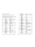
6 Refer to item 1 in the construction illustration on the following page(3)Maximum working voltage - the WSL is not voltage sensitive, but is limited by Power / energy dissipation and is also not ESD sensitiveDIMENSIONS in inches (millimeters)Notes 3D models available: Surface mount solder profile recommendations: SPECIFICATIONSPARAMETERUNITWSL resistor CHARACTERISTICSC omponent temperature coefficient (including terminal) (1) TCR measured from -55 C to 150 Cppm/ C 75 for 7 m to 110 for 5 m to m 150 for 3 m to m 275 for 1 m to m 400 for m to m Element TCR (2)ppm/ C< 20 Operating temperature range C-65 to +170 Maximum working voltage (3)V(P x R)1/2 MODELRESISTANCERANGE ( )DIMENSIONSSOLDER PAD DIMENSIONSLW H to ( ) ( ) ( ) ( ) ( ) ( ) ( )
7 To ( ) ( ) ( ) ( ) ( ) ( ) ( ) to ( ) ( ) ( ) ( ) ( ) ( ) ( ) to ( ) to ( ) to ( ) ( ) ( ) ( ) ( ) ( ) ( ) to ( ) ( ) ( ) ( ) to ( ) ( ) ( ) ( ) ( ) ( ) ( ) to ( ) to ( ) ( ) ( ) to ( ) ( ) ( ) to ( ) ( ) ( ) ( ) ( ) ( ) ( ) to ( ) ( ) ( )LTWHlbaTypical sensing Dale Revision: 02-May-20183 Document Number: 30100 For technical questions, contact: DOCUMENT IS SUBJECT TO CHANGE WITHOUT NOTICE.
8 THE PRODUCTS DESCRIBED HEREIN AND THIS DOCUMENTARE SUBJECT TO SPECIFIC DISCLAIMERS, SET FORTH AT CONSTRUCTION 2816, 2512, 2010, 1206 CLAD CONSTRUCTION 0805 and 0603 Notes Embossed carrier tape per EIA-481(1)Additional packaging details at 65 - 50 - 25 0 25 50 75 100 125 150170 Ambient Temperature in C Rated Power in %IILLLLUSTRATAAIVEPURRPPOSEESSOONLYYLLLL click to get started1) Resistive element: solid Metal nickel-chrome or manganese-copper alloy resistive element with low TCR (< 20 ppm/ C)2) Plated terminal: Solid copper, 100 % Sn (100 " min.
9 With 100 % Ni (20 " min.) under layer finish3) Terminal / element weld4) Silicone coating with ink print23141) Resistive element: Ni-Cr2) Terminal: Solid copper, 100 % Sn (100 " min.) with 100 % Ni (20 " min.) under layer finish3) Terminal to element weld4) High temperature encapsulant: siliconized polyester coating material1432 PERFORMANCETESTCONDITIONS OF TESTTEST LIMITST hermal shock-55 C to +150 C, 1000 cycles, 15 min at each extreme % + Short time overload5 x rated Power for 5 s % + Low temperature operation-65 C for 24 h % + High temperature exposure 1000 h at + 170 C % + Bias humidity+85 C, 85 % RH, 10 % bias, 1000 h % + Mechanical shock100 g s for 6 ms, 5 pulses % + VibrationFrequency varied 10 Hz to 2000 Hz in 1 min.
10 3 directions, 12 h % + Load life1000 h at rated Power , + 70 C, h ON , h OFF % + Resistance to solder heat+260 C solder, 10 s to 12 s dwell, 25 mm/s emergence % + Moisture resistanceMIL-STD-202, method 106, 0 % Power , 7a and 7b not required % + PACKAGING (1)MODELREELTAPE WIDTHDIAMETERPIECES/REELCODEWSL06038 mm/punched paper178 mm/7"5000 EAWSL08058 mm/punched paper178 mm/7"5000 EAWSL12068 mm/embossed plastic178 mm/7"4000 EAWSL201012 mm/embossed plastic178 mm/7"4000 EAWSL251212 mm/embossed plastic178 mm/7"2000 EAWSL281612 mm/embossed plastic178 mm/7"2000 EHLegal Disclaimer Revision: 08-Feb-171 Document Number.