Transcription of POWER MODULE PART #64.10 - Neuspeed
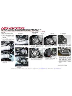
1 Neuspeed 3300 Corte Malpaso Camarillo, CA 93012 FAX POWER MODULE part # FITS: AUDI A3/TT TSI w/MAF (Gen 2) AND VW GTI, Jetta, Passat, CC, EOS, Tiguan TSI w/MAF (Gen 2) Transverse PARTS LIST: 1 POWER MODULE 4 - CABLE TIE TOOLS REQUIRED: 1 T25 TORX (Audi) 1 Jack 1 ADHESIVE BACKED VELCRO 1 T40 TORX (Audi) 2 Jack Stands NOTE: Recommend to use Scan Tool to check ECU for no fault code(s). 1. Recommend to install on cool engine. Lift up engine cover to remove. 2. Clean surface on front side of fuse box or a preferred flat spot on left side of engine bay and stick-on Neuspeed POWER MODULE with supplied Velcro. 3. Sensor Location: RPM Sensor is on top of the valve cover.
2 Boost Sensor is on the plastic Air Charge Pipe located behind cooling fan. Wastegate Control Valve is located underneath on rear corner side of turbo inlet housing. (passenger side). Route harness connectors to their designated sensors. 4. RPM Sensor: Squeeze locking tab to disconnect electrical connection. TIP: Push in on connector while squeezing tab, then pull. 5. Connect Neuspeed POWER MODULE harness in-line as shown. 6. Boost Sensor: Located in Air Charge Pipe behind cooling fan. Connect Neuspeed POWER MODULE harness in-line as shown. 7. Park vehicle on a flat, level surface capable of supporting the vehicle s weight on a jack and jack stands. Using the manufacture s recommended lifting point(s), raise front of vehicle and support with jack stands.
3 NEVER WORK ON A VEHICLE SUPPORTED ONLY WITH A JACK! 8. Wastegate Control Valve: From underneath vehicle the Wastegate Valve is located in the right rear (passenger side) corner of turbo inlet housing. Removal of full length engine splash pans required to access connector. 9. Connect Neuspeed POWER MODULE harness in-line as shown. Then lower vehicle to ground. NOTE: Use cable tie to hold up harness away from drive axle. 10. Attach ground wire to grounding terminal. 11. Cable-tie Neuspeed harness to appropriate places (Blue arrows in step #3). 12. Re-install engine cover. 13. Neuspeed POWER MODULE has (2) switches accessible from the back side to adjust boost settings. Remove plastic cap to access.
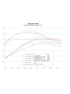
4 NOTE: MODULE preset to LOW +5psi +5 PSI: Switch #1 Down-Switch #2 Down +8 PSI: Switch #1 Up-Switch #2 Down Stock PSI: Switch #2 UP 14. ECU trims will adapt within 10 miles of driving. TIP: Aggressive Sport Driving, recommend to turn OFF ASR (Traction Control) if excessive wheel spin or tire traction loss occurs. Copyright 2016, Neuspeed . All rights reserved. Reproduction in whole or in part prohibited. DOC. Rev. Neuspeed 3300 Corte Malpaso Camarillo, CA 93012 FAX POWER MODULE part # FITS: AUDI A4/A5/Q5/A6 TFSI w/MAF (Gen 2) Longitudinal PARTS LIST: 1 POWER MODULE 4 CABLE TIE 1 ADHESIVE BACKED VELCRO NOTE: Recommend to use Scan Tool to check ECU for no fault code(s).
5 1. Recommend to install on cool engine. Lift engine cover to remove. 2. Clean surface on firewall or a preferred flat spot on left side of engine bay and stick-on Neuspeed POWER MODULE with supplied Velcro. 3. Sensor Location: RPM Sensor is on top of the valve cover. Boost Sensor is on the plastic Air Charge Pipe located on left side of engine (drivers side) behind headlight. Wastegate Control Valve is located on front side of turbo (passenger side). Route harness connectors to their designated sensors. 4. RPM Sensor: Pull out Grey locking tab then squeeze locking tab to disconnect electrical connection. TIP: Push in on connector while squeezing tab, then pull.
6 5. Connect Neuspeed POWER MODULE harness in-line as shown. 6. Boost Sensor: Located in Air Charge Pipe behind headlight. Connect Neuspeed POWER MODULE harness in-line as shown. 7. Remove air duct for easier access to Wastegate Control Valve. 8. Connect Neuspeed POWER MODULE harness in-line as shown. 9. Attach ground wire to grounding terminal on strut tower. 10. Cable-tie Neuspeed harness to appropriate places (Blue arrows in step #3). 11. Re-install engine cover. 12. Neuspeed POWER MODULE has (2) switches accessible from the back side to adjust boost settings. Remove plastic cap to access. NOTE: MODULE preset to LOW +5psi +5 PSI: Switch #1 Down-Switch #2 Down +8 PSI: Switch #1 Up-Switch #2 Down Stock PSI: Switch #2 UP 13.
7 ECU trims will adapt within 10 miles of driving. TIP: Aggressive Sport Driving, recommend to turn OFF ASR (Traction Control) on FWD vehicles if excessive wheel spin or tire traction loss occurs. Copyright 2016, Neuspeed . All rights reserved. Reproduction in whole or in part prohibited. DOC. Rev.