Transcription of Power transformer maintenance. Field testing.
1 1 Power transformer maintenance . Field testing . Andr s Tabernero Garc a Hardware Project Manager Unitronics, Introduction The politic change in some companies had a great influence in maintenance and operation works in their electric machines. Those, have seen many times a decrease in maintenance works allowing a cost decrease in a short term but generating a greater risk of use of them in a mean and long term. The operating conditions also have changed in the sense of taking the maximum advantage of each machine making it work at the maximum possible ratings and some times above nominal values. This situation trends to premature age the machine fleet and if those are not part of a minimum maintenance program detecting risk situations or load limitation, the resultant situation will lead in a mean time to an irregular manoeuvre Field (breakdowns, forced outages, supply ) that today are so usual and negative to the end customer.
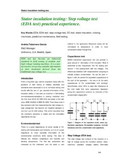
2 FIG 1. Breakdown of the dielectric system in a Power transformer column. Courtesy from Electric Works Molina, C rdoba. 2 Power transformer is an electric machine with a useful life cycle of some 30 years. This doesn t mean to say that cannot be used above this time, in fact, a great part of the electric and industrial fleet is being operated with reliable machines above this time. The really important fact is to know the status and evolution of the transformer to be in conditions to operate it with the maximum security and know if it is appropriate to continue it s use, know overload capacity, limit load, refurbish it or either take it out from active service.
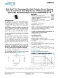
3 There is a group of maintenance techniques that from an electric point of view and through some Field tests are going to allow us to trace the transformer status as indicated and in the case of breakdown diligently detect the real problem and perform the required actions. FIG 2. Field testing of a Power transformer before putting into service (50 MVA). Power transformers Field testing . As a result of the owner company, the importance of the machine and the outage possibilities, it is necessary to perform on each transformer a fitted maintenance program with a test protocol previously accorded. Next will be indicated a series of test that can set up this program and that are something like a continuation of validation tests performed when manufacturing the transformer but adapted to Field testing .
4 We have to take under account that in the Field , in transformer installations, is not usually possible to have bulky equipments, what states certain limitations to Field test with respect to manufacturing ones. Described tests are chosen from the commercially available ones, standardized and usual into test programs. 3 MAGNETIC / ELECTRIC CIRCUIT TESTS. Those will be performed wit portable instrumentation (easily transported in vehicle/test van) of a series of measurements that allow obtaining base parameters from the transformer . It will be studied the punctual status to perform a diagnose and parameter trending values to perform scheduled works.
5 All this tests are off-line. Electric/Magnetic Field testing : No-load test. Turns Ratio (TTR). Polarity, connection group y excitation current. Load test (short circuit test, impedance measurement). Winding resistance. Frequency response analysis (FRA). - No-load test. Turns Ration. Polarity, connection group and excitation current. This test usually known as no load test and involves inserting an alternating voltage in the high voltage winding of the transformer in each of it s phases with low voltage side open. With the result values can be obtained basic parameters from the transformer : transformer Turns Ratio (TTR): quotient between high voltage / low voltage.
6 Must match with protocol /nameplate values. FIG 3. Monophase transformer turns ratio unit, from Megger Company, model TTR100. In the Power transformer with tap changer you will take advantage to make the register of each position from it giving extra information on its status and that of the On Line Tap Changer (OLTC). This measurement will directly inform of the existence of shorts between turns. 4 FIG 4. Results of a turns ratio test determining a short circuit between turns at low voltage side . Diagnose software from ETP system (TRR unit UM1B from UNITRONICS). Red and green phases over imposed, yellow separated. Polarity / connection group. Connection group can also be checked with the previous results and aided with voltage diphase between high / low voltage.
7 FIG 5. 3-phase transformer Turns Ratio Meter Unit from UNITRONICS Company, model UM1B. Excitation current. It s the current flowing into the high voltage winding with the low voltage side open. This current should be proportional to the No-load acceptance test but with the difference resultant from the use of test voltages different from nominal values. 5 FIG 6. transformer Turns Ratio Meter Unit from Megger Company, model TTR. It shouldn t exist excessive deflection from values measured between phases and its normal a slight difference (geometric) between extreme and central windings. It will exist great changes when appear heat points, degradation in the magnetic package, loose core or detached magnetic shunt.
8 - Load test (short circuit test, Impedance measurement). This test usually known as short circuit test is based in the insertion of a voltage in one winding (high voltage one) with the other winding short-circuited. This test simulated the factory one but its not at all comparable in results because of not flowing nominal values. It is usual to register nominal and extreme positions if the transformer had an OLTC. FIG 7. 3phase short circuit impedance unit from UNITRONICS company, model UM5B. Short circuit voltage. This parameter usually expressed in % and identified in the nameplate of the transformer is the extrapolated result from the test voltage to 6 nominal voltage and should be near the protocol /nameplate value from the transformer .
9 It s change will indicate irregularities in the magnetic core, winding displacement, short-circuits, mechanical FIG 8. Results screen from a short circuit test (unit UM5B, UNITRONICS company) indicating changes in the geometric circuit. - Winding Resistance. With this test we search determinate the pure ohmic resistance from each phase windings both in high and low voltage and it exist a tap changer in each position. What in a first approach can be easy to measure, its not so, because it is necessary to make flow relatively high currents to register the usual low resistance values /m / with the required precision. This currents must also flow through the equivalent inductances of the transformer .
10 7 FIG 9. Results from a Winding resistance test showing a problem in the high voltage winding (system UM3B, UNITRONICS Company). The high inductive character of Power transformers (Equivalent L and magnetic core) implicates magnetization time and measurement stabilization should be taken under account while determination the measurement end and give the results. FIG 10. 3-phase winding resistance meter from UNITRONICS Company, model UM3B. This has more relevance in high Power transformers or from special designs or configurations. 8 FIG 11. Detected fault in an OLTC from the previous test results. Final results must be temperature normalized to get results comparable in time and compose parameters must be converted into simple ones (this is, when measuring a Wye and the measure was performed between phases without; should extract each phase winding values separately).