Transcription of POWER TRANSMISSION SYSTEM - hillagric.ac.in
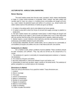
1 AG ENGG 243 Lecture 8 1 POWER TRANSMISSION SYSTEM TRANSMISSION is a speed reducing mechanism, equipped with several gears (Fig. 1). It may be called a sequence of gears and shafts, through which the engine POWER is transmitted to the tractor wheels. The SYSTEM consists of various devices that cause forward and backward movement of tractor to suit different field condition. The complete path of POWER from the engine to the wheels is called POWER train. Function of POWER TRANSMISSION SYSTEM : (i) to transmit POWER from the engine to the rear wheels of the tractor, (ii) to make reduced speed available, to rear wheels of the tractor, (ii) to alter the ratio of wheel speed and engine speed in order to suit the field conditions and (iv) to transmit POWER through right angle drive, because the crankshaft and rear axle are normally at right angles to each other.
2 The POWER TRANSMISSION SYSTEM consists of: (a) Clutch (b) TRANSMISSION gears (c) Differential (d) Final drive (e) Rear axle (f) Rear wheels. Combination of all these components is responsible for TRANSMISSION of POWER . CLUTCH AND FLUID COUPLING CLUTCH: Clutch is a device, used to connect and disconnect the tractor engine from the TRANSMISSION gears and drive wheels. Clutch transmits POWER by means of friction between driving members and driven members. Necessity of clutch in a tractor: Clutch in a tractor is essential for the following reasons: (i) Engine needs cranking by any suitable device. For easy cranking, the engine is disconnected from the rest of the TRANSMISSION unit by a suitable clutch. After starting the engine, the clutch is engaged to transmit POWER from the engine to the gearbox.
3 (ii) In order to change the gears, the gearbox must be kept free from the engine POWER , otherwise the gear teeth will be damaged and engagement of gear will not be perfect. This work is done by a clutch. (iii) When the belt pulley of the tractor works in the field it needs to be stopped without stopping the engine. This is done by a clutch. Essential features of a good clutch: (i) It should have good ability of taking load without dragging and chattering. (ii) It should have higher capacity to transmit maximum POWER without slipping. (iii) Friction surface should be highly resistant to heat effect. (iv) The control by hand lever or pedal lever should be easy. Fig 1 POWER TRANSMISSION SYSTEM of Tractor AG ENGG 243 Lecture 8 2 TYPES OF CLUTCH (1) Friction clutch (2) Dog clutch (3) Fluid coupling. FRICTION CLUTCH: Friction clutch produces gripping action, by utilising the frictional force between two surfaces.
4 These surfaces are pressed together to transmit POWER . While starting the engine, the clutch pedal is depressed. After the start of the engine, the clutch pedal is slowly released to increase the pressure box for onward TRANSMISSION to the rear wheels. This pressure is obtained by a set of heavy springs, fitted together in housing. Engagement and disengagement of this type of clutch is very smooth due lo larger surface area of friction members. Dog clutch: It is a simple clutch having square jaws, which are used to drive a shaft in either direction. It is mostly used in POWER tillers. Fluid coupling: Fluid coupling consists of a driving member and a driven member. An impeller with radial- vanes constitutes the driving member and runner with radial vanes constitutes the driven member. The entire unit is housed in a suitable casing.
5 A coupler is mounted on the engine crankshaft and is 3/4th filled with suitable oil. A spring loaded sealing ring is provided to make the driven shaft oil tight. At the rotation of the crankshaft, the oil is thrown out by centrifugal force from the centre to the outer edge of the impeller, increasing the velocity and the energy of the oil. It then enters the runner vanes at the outer portion and flows towards the centre, causing rotation to the runner unit. As long as impeller and runner rotate at different speeds, the oil continues to circulate uniformly but when the impeller and runner start running at same speed, the circulation of oil stops. The coupling does not increase the applied torque but only transmits the torque in a uniform manner. The main features of fluid coupling are: (i) Absorption of shock and vibration (ii) Smooth starting and (ii) Easy operation.
6 TRANSMISSION GEARS AND TORQUE CONVERTER GEAR A tractor engine runs at high speed, but the rear wheel of the tractor requires POWER at low speed and high torque. That's why it becomes essential to reduce the engine speed and increase the torque available at the rear wheels of the tractor because 45002 NTBHP = Where T is torque in kg-m and N is rev/min. If the engine hp is constant, it is obvious that for higher torque at wheels, low speed is required and vice versa. So the gearbox is fitted between engine and rear wheel for variable torque and speed. This is done by suitable design of gear and shafts (Fig. 4). Speed varies according lo the field requirements and so a number of gear ratios are provided to suit the varying conditions. Gears are usually made of alloy steel. As the tractor has to transmit heavy torque all the time,-best quality lubricants free from sediments, grit, alkali and moisture, is used for lubrication purpose.
7 SAE 90 oil is generally recommended for gearbox. Common gears used on tractors are of two types: Fig. 2 Single plate clutch Fig 3 Fluid coupling AG ENGG 243 Lecture 8 3(i) Selective sliding type (ii) Constant mesh type. (i) Selective sliding type: The gear box consists of: (i) gear housing (ii) gear shifting lever (iii) main shaft or input shaft (iv) output shaft and (v) lay shaft or countershaft. A number of gears are mounted on these shafts (Fig. 5). The main shaft is directly connected to the clutch and carries gears. The gears are liable to slide. The gears are shifted with the help of shifting lever and shifting fork. The gears are shifted along the shaft, to which they are splined to engage with another gear as and when desired to connect the POWER train. The gears are of different diameters having different number of teeth. Speed is reduced in proportion to the number of teeth provided on the gears.
8 (ii) Constant mesh type: These gears are always in mesh. Usually the gears arc helical in shape. The TRANSMISSION is put into operation by engagement of shifting couplings, which slide along the splines on the countershaft and the output shaft of the gear box. DIFFERENTIAL UNIT AND FINAL DRIVE Differential: Differential unit is a special arrangement of gears to permit one of the rear wheels of the tractor to rotate slower or faster than the other. While turning the tractor on a curved path, the inner wheel has to travel lesser the tractor to move faster than the other at the turning point. The output shaft coming from the gear box is provided with a bevel pinion at the end of the shaft (Fig. 6). The bevel pinion is in mesh with a large bevel wheel known as crown wheel. The main functions of crown wheel assembly are: (i) to transmit POWER through right angle drive to suit the tractor wheels.
9 (ii) to reduce the speed of rotation. The differential unit consists of: (i) differential casing (ii) differential pinion (iii) crown wheel (iv) half shaft and (v) bevel gear. Fig 4 TRANSMISSION gears Fig 5 Sliding type gearbox for 4 speeds AG ENGG 243 Lecture 8 4 The differential casing is rigidly attached with the crown wheel and moves like one unit. Two pinions are provided inside the differential casing, such that they are carried round by the crown wheel but they are free to rotate also on their own shaft or stud. There are two or more bevel gears in mesh with differential pinion. One bevel pinion is at the end of each half shaft, which goes to the tractor rear wheel. Thus instead of crown wheel being keyed directly to a solid shaft between the tractor wheels, the drive is taken back from the indirect route through differential casing, differential pinion and half shaft of the tractor.
10 When the tractor is moving in a straight line, the differential pinion do not rotate on the stub shaft but are solid with the differential casing. They drive the two bevel gears at the same speed and in the same direction as the casing and the crown wheel. Each differential pinion can move in two planes simultaneously. When it is carried round by the casing, it drives the half-shaft in the same direction but when it is rotated on its own shaft, it drives them in opposite direction i. e. rotation of differential pinion adds motion to one shaft and subtracts motion from the other shaft. Differential lock: Differential lock is a device to join both half axles of the tractor so that even if one wheel is under less resistance, the tractor comes out from the mud etc as both wheels move with the same speed and apply equal traction.