Transcription of Power Trim and Tilt Systems - West Virginia University
1 Chapter EighteenPower Trim and Tilt SystemsThe MerCruiser Power trim system permitsraising or lowering the stern drive unit for efficientoperation under varying conditions. Early sterndrive units used a mechanical tilt system in theform of a series of holes in the gimbal ring. Afterthe unit was set at the desired angle, an adjustmentstud inserted through the appropriate hole held itin chapter covers three MerCruiser Power trimand tilt Systems : the high-pressure pump system,low-pressure pump system and auto trim PUMP SYSTEMThis MerCruiser Power trim and tilt system electricalsub-system consists of a Power trim control panelor handle, a pump motor and a trim limit switch,with connecting wiring.
2 Some models may also beequipped with a trim indicator sender. Figure 1shows a typical hydraulic sub-system contains a Prestoliteor Oildyne hydraulic pump, the trim cylinders, areverse lock valve and the necessary hoses andfittings. See Figure Sub-systemSingle or dual solenoids may be used accordingto system Solenoid SystemA 3-button Power trim panel control operates thesingle solenoid system shown in Figure 1. Batterycurrent reaches the solenoid through the red lead, ago-amp fuse, a 40-amp circuit breaker and thered/purple lead. Depressing the IN button routescurrent from the red/purple lead to the green /whitewire, operating the pump in the down the UP/OUT button sends currentfrom the red/purple extension lead through thepurple/white lead to the trim limit switch.
3 Currentreaching the switch passes through the blue/whitelead to the solenoid, where it travels to the trimmotor through a larger blue/white lead. The trimmotor can provide about 17 of trim before thetrim limit switch opens and shuts off current to the UP/OUT and UP switches at thesame time allows the current to bypass the trimlimit switch. It passes from the red extension leadto the blue/white wire and on to the solenoid todrive the unit to its full up EIGHTEEN01 TYPICAL POWERTRIM AND TILT SYSTEM(HIGH PRESSURE PUMP)Dual Solenoid SystemPump ProtectionA dual solenoid trim pump is generally usedIn each system, a bi-metal switch built into thewhen an in-handle trim control is required or whenbrush lead protects the pump motor fromthe harness length would cause an excessive voltageoverheating.
4 If the motor continues to operate afterdrop. The circuitry and its operation is similarthe cylinders are extended, the high amperage(Figure 3), with one solenoid controlling the up opens the circuit as soon as the brush leadfunction and the other operating the down temperature becomes excessive. Once the , the switch closes to allow normal TRIM AND TILT SYSTEMS535 Trim Limit/Trim PositionSender SwitchesThe trim limit (TL) switch is located on the leftside of the gimbal housing. This switch permitsonly a limited amount of outward trim travel toprovide safe control at high speeds and preventdamage to drive unit or trim cylinder due to lostside support of drive trim position (TP) sender is installed on theopposite (starboard) side.
5 If not equipped with atrim position gauge, an empty and unmarkedhousing is installed in place of the TP Limit SwitchTesting1. Disconnect the trim limit switch bullet leadsfrom the trim control harness inside the boat (seeFigure 1 or Figure 3).2. Connect an ohmmeter to the switch bullet should show continuity with drive unit indown Operate Power trim and note meter reading. Atabout one-third trim travel, the switch should openand the meter should show no If the switch does not perform as specified inStep 2 or Step 3, remove it from the gimbal Step 2 and Step 3 while operating switchmanually. The ohmmeter should show a lack ofcontinuity twice in every 360 revolution when theswitch is operated Replace the switch if it does not operate Position Sender Testing1.
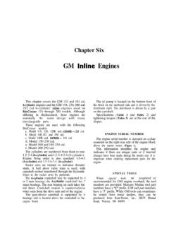
6 Disconnect the indicator leads from theterminal block on the harness plug Connect an ohmmeter to the Start with the unit in a down position and trimthrough the total travel range, watching the should show a smooth progression from zerothrough 80 ohms (dual station sender) or 160 ohms(single station sender). the meter needle does not move or if it moveserratically, remove the sender and repeat the test. Iferratic or no movement is still noted with thesender off the gimbal ring, replace the SUB=SYSTEM( UP CIRCUIT SHOWN)IIC---411 1 O-ringTwo trli cylinders(one shown)up and down same for valvein closed positionin reverse only(late type valve)18536 CHAPTER EIGHTEEN5.
7 If the meter needle responds correctly with thesender unit removed, check the hinge pin whiletrimming the unit up and down. If there is no hingepin movement, lubricate it with Anti-CorrosionGrease (part No. C-92-74048).Trim Limit/Trim PositionSender Switches Replacement1. Remove 2 screws, lo&washers and retainersholding switch/sender to the gimbal ring. Removethe Disconnect 2 wires from back of switch/sender3. Reconnect wires to back of new screws securely and fill grooves withAnti-Corrosion Lubricant (part No. C-92-74048).Be sure screws are completely Align slots on insulator with rear of housingassembly and Align index on rotor with housing index.
8 Installassembly on gimbal ring with bell housing in down Install switch/sender attaching screws withlo&washers and Reconnect leads inside Adjust switch/sender as described in TRIM AND TILT SYSTEMSTRIM LIMIT SWITCH ADJUSTMENTA. Gimbal ring support boss0. 314 inchC. 1 inchD. Drive shaft housing edgeTRIM SWITCH/SENDERA. Retaining screwsB. Adjusting slotsTrim Limit Switch Adjustment1. Trim the drive unit upward until the front edgeof the drive shaft housing protrudes 3/4-l in. intothe gimbal ring support bosses. See Figure Disconnect switch bullet leads at harness insideboat. Connect an ohmmeter to disconnected Loosen trim limit switch retaining Watch ohmmeter and rotate switch housing ineither direction until the switch circuit just Tighten retaining screws.
9 Reconnect leads toharness inside Position Sender Adjustment1. Place drive unit in full down Loosen trim position sender retaining Figure Turn ignition key to Rotate sender housing in either direction untilpower trim gauge needle rests at bottom of Tighten retaining screws. Recheck instrumentreading and turn ignition key Indicator Gauge Testing1. Check gauge terminals and connections forlooseness or corrosion. Correct as Disconnect leads at gauge Connect a jumper lead between the red wireterminal on the ignition switch and the terminalmarked IGN on the indicator gauge. The gaugeneedle should deflect beyond the red With jumper lead still in place, ground othergauge lead to gauge case.
10 Needle should deflectback past the green arc If needle does not react as specified in eitherStep 3 or Step 4, replace the Trim Test SequenceThe control box harness connectors must bedisconnected and the key switch must be OFF forthe following test procedures. The tests are given inthe sequence of likely component failure. Makesure that the jumper lead is installed betweenterminals 3 and 5 only when specified. Refer toFigure 6 for this series of test UTIONC ontrol box terminals 2 and 3 carry 12 volts atall times. Exercise caution when testing in ornear the area of these terminals, as a short coulddamage the control box or your test EIGHTEENNOTES:1.