Transcription of POWERCON CORPORATION
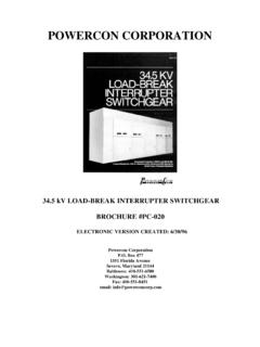
1 POWERCON CORPORATION . 5kV &15Kv METAL-CLAD SWITCHGEAR. BROCHURE #PC042. ELECTRONIC VERSION CREATED: 6/30/96. POWERCON CORPORATION Box 477. 1551 Florida Avenue Severn, Maryland 21144. Baltimore: 410-551-6500. Washington: 301-621-7400. Fax: 410-551-8451. email: METAL-CLAD VACUUM SWITCHGEAR. This bulletin describes Metal-Clad Switchgear - one application, manufacture, delivery, and service of of POWERCON 's Switchgear product lines. Power Systems Switchgear. This advanced switchgear line is completely This product is the result of seasoned technical factory built, wired and assembled. Each cubicle efforts combined with the well versed, skilled may contain the circuit breaker, bus bars, primary competent, veteran work force exerting their and secondary disconnecting devices, instrument combined efforts to provide the best in service and transformers, instruments and relays, secondary equipment.
2 Wiring and other necessary corn The switchgear is designed so that additional circuit breaker or Our membership in NEMA, ANSI and IEEE keep us auxiliary cubicles may be added in the future. up to date on the ever changing standards so that we meet today's exacting demands. The Circuit Breaker An all inclusive METAL-CLAD equipment Vacuum interrupters with stored energy designed, built and tested to the applicable industry operating mechanism standards shown in Table 1. Primary disconnecting devices Auxiliary switches PORCELAIN (the near ultimate in insulation) for Ground contacts all live part supports including the circuit breaker Control wiring itself, is available. Interlocks Compartmented cable, bus, fuses, voltage and In addition to the standard equipment described, auxiliary transformers.
3 Custom engineered switchgear is offered to meet individual purchaser needs. An interlock system to: With a highly skilled professional engineering Prevent breaker closing except in "connect", manufacturing team, an organizational entity has test , or ' disconnect position. been developed to provide the material and services Interference for prevention of any but proper our customers require. The engineering staff - breaker to be inserted in cell. application product design - development - Spring discharge prior to removal from cell. manufacturing - has achieved the extensive system experience and knowledge required in the (For Guide Specifications - See Publication PC-029). Table 1 - Applicable Industry Standards American National Standards Institute (ANSI) National Electrical Manufacturers Association (NEMA).
4 70 East 40th Street 2101 L Street , Suite 300. New York, New York 10017 Washington, 20037. Standard No Description Standard No. Description CA High-Voltage Circuit Breaker Rating SG-2 High Voltage Fuses Structure Preferred Ratings of AC. High-Voltage Circuit Breakers Test Procedures for AC High- SG-4 Power Circuit Breakers Voltage Circuit Breakers Application Guide for AC. High-Voltage Circuit Breakers AC High-Voltage Circuit SG-5 Power Switchgear Assemblies Breakers Control Requirements Switchgear Assemblies and Metal-Enclosed Bus Definitions of Power Switchgear HORIZONTAL DRAWOUT. 15kV 500 MVA Indoor Line-Up Preferred Ratings for Indoor Oilless Circuit Breakers Table 2 - ANSI - 1987. Rated Max. Rated Voltage Rated Rated Short- Rated Rated Max. Max. Closing and Voltage (1) Range Factor Continuous Circuit Current Interruption Voltage Divided Symmetrical Latching kV, ms K (2) Current at 60Hz (at Rated Time by K Interrupting Capability (3) maximum kV) (7) kV, rms Capability and times Rated Amperes, rms (4) (5) (6) (9) Cycles Rated Short- Short-Circuit AK, rms Time Current Current, (4).
5 (4) (5) (8) kA, Crest kA, rms 1200 5 12 32. 1200,2000 29 5 36 97. 1200,2000, 41 5 49 132. 3000. 1200,2000 33 5 41 111. 1200,2000 18 5 11-5 23 62. 1200,2000 28 5 36 97. 1200,2000, 37 5 413 130. 3000. 1200,2000, 21 5 35 95. 3000. 1200,3000 40 5 40 108. For service conditions, definitions, and (2)The rated voltage range factor, K, is the ratio of interpretations of ratings, tests, and qualifying terms, rated maximum voltage to the lower limit of the see ANSI/IEEE , ANSI/IEEE range of operating voltage in which the required 1979, and ANSI/IEEE symmetrical and asymmetrical current interrupting capabilities vary in inverse proportion to the Current values have been rounded off to the nearest opening voltage. kilo-ampere (kA) except that two significant figures are used for values below 1 OkA.
6 (3)The 25-Hz continuous current ratings in amperes are given herewith following the respective 60Hz (1)The voltage rating is based on ANSI , rating: 600-700; 1200-1400; 2000-2250; 3000- where applicable, and is the maximum voltage for 3500. which the breaker is designed and the upper limit for operation. (4) Related Required Capabilities The following related required capabilities are associated with the short circuit current rating of the circuit breaker. For operating voltages below 1/K times rated maximum voltage. the required symmetrical current (a) Minimum symmetrical interrupting interrupting capabilities of the circuit breaker shall capability (kA. mm) of the circuit breaker is equal be equal to K times rated short circuit current. to K times rated short circuit current.
7 (6) With the limitation stated in of (b) 3-second short time current carrying ANSI/IEEE all values apply for poly- capability (kA, rms) of the circuit breaker is equal phase and line-to-line faults. For single phase-to- to K times rated Short-Circuit current. ground faults, the specific conditions stated in of ANSI/IEEE apply. (c) Closing and latching capability (kA, rms) of the circuit breaker is equal to K times rated (7) The ratings in this column are on a 60-Hz basis Short-Circuit current. If expressed in peak and are the maximum time interval to be expected amperes, the value is equal to K times rated during a breaker opening operating between the short circuit current. instant of energizing the trip circuit and interrupting of ht main circuit on the primary arcing contacts (d) 3-Second short-time current carrying under certain specified conditions.
8 The values may capability and closing and latching capability are be exceeded under certain conditions as specified in independent of operating voltage up to and of ANSI/IEEE , including rated maximum voltage. (8) Current values in this minimum are not to (5) To obtain the required symmetrical current be exceeded even for operating voltages below I/K. interrupting capability of a circuit breaker at an times rated minimum voltage. For voltages between operating voltage between 1/K times rated maximum rated maximum voltage and 1/K times rated voltage and rated maximum voltage, the following maximum voltage, follow (5) above. formula shall be used: (9) Rated permissible tripping delay time (Y) = 2. Required symmetrical current interrupting seconds. capability=.
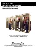
9 Rated short circuit current X (rated maximum voltage). (operating voltage). 3. METAL-CLAD SWITCHGEAR HORIZONTAL DRAWOUT. See Guide Specifications - See Publication PC-029. It Consists Of: The breaker, bus, potential transformers, current transformers and cables all have their own compartments. And, each function is isolated by rugged partitions. Framework of welded steel Sheet steel enclosure, including a hinged front door, which POWERCON metal-clad provides the value of a superior may be used as an instrument panel insulation system at vital points, and greater structural Compartment and inter-unit barriers strength from a rugged all-welded steel frame. Three-phase insulated bus and connections Porcelain bus supports available Relays and instrumentation are mounted on the front door so Stationary primary disconnecting devices that the breaker can be removed or inserted without Stationary secondary disconnecting devices damaging a relay.
10 Circuit breaker racking-in device Circuit breaker interlocking device Guide rails are provided so that the breaker will roll into Instruments and relays proper position in the cubicle. The mechanism assures Control wiring perfect alignment when the breaker is racked into its terminal blocks operating position. Instrument transformers Provision for connecting main cable Porcelain - The Ultimate In Insulation Guide rail on floor of structure Wiring channels Control cut-outs LOWER BREAKER COMPARTMENT CONSTRUCTION. FRONT VIEW - DOORS, SHUTTERS AND SHUTTER. ISOLATION BARRIERS REMOVED. UPPER COMPARTMENT SIMILAR IN CONSTRUCTION WHEN. REQUIRED. 1. Upper Primary Disconnects 2. Lower Primary Disconnects 3. Current Transformers 4. Secondary Terminal Blocks 5. Heaters 6.