Transcription of POWERCON CORPORATION
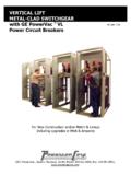
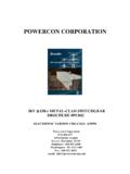
1 POWERCON CORPORATION . kV LOAD-BREAK INTERRUPTER switchgear . BROCHURE #PC-020. ELECTRONIC VERSION CREATED: 6/30/96. POWERCON CORPORATION Box 477. 1551 Florida Avenue Severn, Maryland 21144. Baltimore: 410-551-6500. Washington: 301-621-7400. Fax: 410-551-8451. email: LOAD BREAK INTERRUPTER switchgear . APPLICATION. POWERCON Load Break Interrupter Switches are applied in the control and switching of Power Distribution Systems having nominal voltage ratings from KV to KV. They are capable of switching 600 & 1200 amperes. Table #1 lists the applicable limits and conditions of switching. These switches are available with either electrical or mechanical operators. When used in conjunction with fuses they will afford overload, short circuit and disconnect services.
2 These switches are used: On the primary of transformers for their protection and isolation. For the protection and isolation of single circuit systems. For the protection and isolation of multi-circuit systems. For automatic transfer schemes where their ratings are not exceeded. APPLICABLE INDUSTRY STANDARDS. NEMA SG-5 - Power switchgear Assemblies NEMA SG-6 - Power Switching Equipment ANSI - switchgear Assemblies ANSI - Requirements for High Voltage Air Switches ANSI - indoor Apparatus Insulators (For High Voltage Switches). ANSI - Preferred Ratings and Mfgr Specs for High Voltage Switches ANSI - Rated Control Voltages and Ranges for High Voltage Switches ANSI - Test Code for High Voltage Air Switches TABLE #1. indoor AIR INTERRUPTER SWITCH RATINGS.
3 (These ratings apply to Switches & Equipments with Stored Energy Operated Switches). (Special Ratings Available - Consult Factory). Voltage Ratings Current Ratings Nominal KV Max. Design 1 MIN. Power x 50 Impulse Continous Contact Moment 3 Sec. Fault RMS Kv RMS Wtishstand KV Freq. Withstand AMP RMS Interupting ary KA RMS Close RMS KV BIL Rating AMP Assym. Assym. RMS KA RMS KA. RMS. 19 60 600 600 40 25 40. 1,200 1,200 61 38 61. 26 75 600 600 40 25 40. 1,200 1,200 61 38 61. 36 95 600 600 40 25 40. 1,200 1,200 61 38 61. 50 110 600 600 40 25 40. 1,200 1,200 61 38 61. 60 125 600 600 40 25 40. 1,200. 80 150 600 600 40 25 40. 1,200. 95 200 600 600 40 25 40. 1,200. METAL ENCLOSED switchgear - AN ECONOMICAL METHOD FOR POWER. DISTRIBUTION. PIF FRAME MOUNTED HEAVY DUTY RUGGED INDUSTRIAL.
4 LOAD BREAK SWITCHES WITH SUPERIOR FEATURES PROVIDE: ARCING CHAMBERS. Tungsten material stationary arcing contacts are located inside the arc chutes. They remain at the same potential as the main stationary contact. As the quick break blade is withdrawn from the arc chute it parts with the stationary arcing contacts inside the chute. The chute is made from a specially prepared compound that evolves a gas to quickly extinguish the arc. Clean consistent interruptions result. No appreciable amounts of gas are evolved. MAIN MOVEABLE BLADES. These blades are made of 99% conductivity hard drawn ETP copper bars and they are heavily silver-plated at the contact points for long dependable operation. QUICK BREAK BLADE. The quick break arcing blade is made of a special high strength, hi conductivity material tipped with a tungsten arcing material.
5 A quick break spring charging mechanism is mounted on the blade that with an assist from the arcing chamber stationary contacts prevents the opening until after the main contacts part at the proper clearance spacing. PORCELAIN SWITCH INSULATORS. The near ULTIMATE in insulation Wet process porcelain is used as the insulating support for the main hinge and jaw contacts. Porcelain is a tried and true material proven in service as the near ultimate in insulation. It has excellent dielectric characteristics, is non- tracking, non-combustible, non-hygroscopic, won't age, and is easy to clean. No organic materials can compare to the performance of porcelain. A SUPER STRUCTURE. POWERCON 's all welded frame design provides a ruggedness and greater structural strength which is in a class b@ itself.
6 The jig welded structural members form an assembly to provide ii plumb and square switch unit. This assures interchangeability of units and results in a minimum of installation time. STATIONARY ARCING TIPS. POWERCON arcing blades and tips are designed to prevent arcing blades from hanging up in the stationary arcing contacts. Successful tests with welded stationary contacts have been made and it has been successfully demonstrated that these tips do not hang up. POWERCON Load Break Switches Provide: Unequaled Dependability Minimum Maintenance Long Interrupting Life Greater Safety Simple to Install and Operate STATIONARY CONTACTS. Both hinge and jaw contacts are heavy copper castings capable of absorbing and dissipating the heating from the large short circuits which may be encountered.
7 The contact pressure is maintained on these contacts with selected spring washers especially adapted to maintain suitable pressure for many operations and over many years of operational performance. The retaining nuts are Elastic-Stop-nuts to prevent vibration, shock, and operation loosening the joint. Special dirt sealing designs effectively prevent the entrance of dust or dirt into the contact making area. The contact area is silver to silver to maintain optimum current carrying ability and decrease heating. STORED ENERGY MECHANISM. The powerful opening and closing springs of POWERCON 's off -center stored energy mechanism provides for quick make (rated fault closing) and quick break (rated load interruption). The switch mechanism shaft is driven by a chain and sprocket from the front operating handle.
8 As the handle is rotated, it is directly connected to a sprocket which in turn, chain drives the opening spring to a "charged" position. As the operator continues to rotate the handle, the charged spring is driven off-center by the chain and releases its energy into rotating the operating shaft to operate. The switch blades will not move, in either a closing or opening direction, until the closing spring causes rotation in the operating shaft. It should be noted, that once the springs are moved off -center,, the operator has no further control of the opening and closing operation. He therefore has a fault closing and rated load break feature independent of his performance. ANTI FRICTION BEARINGS provide for a smooth operating performance. HANDLE HOUSING.
9 POWERCON 's cast aluminum handle housing has provisions for multiple-, padlocking. These handles are non-removable, self-latching, and padlockable in the open and closed positions. Telltale indicators advise operator of switch position. CONSTRUCTION. FINAL ASSEMBLY LINE. Tie Copper Bus to Main Bus Section B' Compartment Arc Chutes Chain Drive Tie Copper Bus to Section A'. Fuses CONSTRUCTION SIDE VIEW. (Note: Porcelain Supports Thru-out). Bus Tie Unit The Ultimate Insulation (Close Up). Main Bus Copper Ground Bus Fuse Assembly Prior Feeder Fused Power Co. Incoming Line to Switch Disconnect Metering Switch Installation Compartment surfaces shall be finished in ANSI No. 61 medium light gray SPECIFICATIONS finish for the indoor switchgear . The complete equipment for outdoor equipment shall be FOR STATIONARY switchgear .
10 Painted with a suitable finish coast of ANSI No. 70 and shall be weatherproofed. Outdoor equipment shall be built on a minimum of 3" at SCOPE. lb/ft channels and shall be gasketed and weatherproofed and equipped with long life tubular heaters. Control power for These specifications describe either indoor or outdoor metal heaters shall be provided from an external service. enclosed, load break interrupter switch equipments consisting Lifting angles or other suitable means for lifting shall be of fused and/or unfused load interrupter switches and auxiliary provided. devices as described and as indicated on attached single-line diagram. It shall consist of one unit or multiple units in BUS DESIGN. accordance with the specific requirements outlined below.