Transcription of PP-D-210079-2 - Solo 3 - Home Install Guide
1 Fast ChargingSolo 3 - HomeInstall GuideSolo 3 - Domestic PP-D-210079-2 Install Guide S3-UK-H-IG Important safety informationThe Solo 3 is designed and manufactured to be safe provided they are professionally installed, used and maintained in accordance with the manufacturer s instructions.
2 They should be installed by approved electrical installers in accordance with national and local regulations applicable at the time of installation, BS7671:2018. The Solo 3 is designed to be connected to one dedicated AC supply only. The property must comply with minimum BS7671 standards before installation commences and the supply must be adequately rated for the additional load required for EV charging. As of the 1st January 2019 either a Type B or a Type A RCD with 6mA DC protection must be used for protection (6mA DC protection is included inside the Solo 3).Important notes: A DC leakage fault in the vehicle may blind a type AC RCD and render it requires a mechanical RCD/RCBO that switches all poles (including neutral) be installed in the circuit and 2 pole isolation for for installThe Solo 3 can be fitted inside or outside.
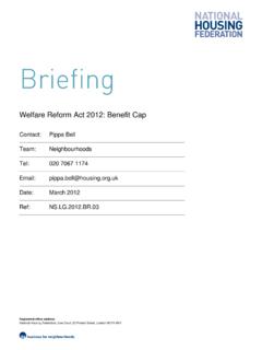
3 The installer should consult the site owner to establish their preferred installation location. This should take into consideration the cable length (distance to vehicle being charged), risk of vehicle impact and obstruction of access code of practice recommends the Solo 3 be mounted to a permanent structure at a height of 750mm-1200mm (see Fig. 1). This is to assist those with accessibility requirements and reduce the risk of vehicle impact. Fig. 1 - Location and dimensions of the Solo 3. This document details the Install guidance for the Solo 3 ( Home) a variant of the Solo product family. If you re unsure which model you have, please contact Pod Point Solo 3 is designed for installations inside or outside, with the advanced safety systems we have built into the charger ensuring its safe usage.
4 This guidance provides information to assist when installing the new Solo 3. This Guide should not be used for any other SocketTetheredSpeed categoryFast ChargingCharging , 7 and 22kW models availableProduct familySoloSolo 3 - HomeUniversal socketed models consider the additional connector for the overall depth from wall when plugged in (approximately 150mm should be added).Solo 3 - Domestic PP-D-210079-2 Install Guide S3-UK-H-IG
5 750-1200mm (code of practice)500-1500mm (BS7671 & BS EN61851)Installation height to centre of socketTechnical detailsThe Solo 3 is a Class I/II rated device, pollution degree 3 for 230V / 400V AC 50Hz systems and is IP54 and IK10 is designed to meet the following European standards: BS EN IEC 61851-1:2019 (BS7671 ), Low Voltage Directive (LVD) 2014/35/EU and electromagnetic compatibility (EMC) Directive 2014/30/EU. Sockets and EV charging connectors comply with IEC manufacture, each Solo 3 has been functionally tested for safety using BS EN 61010 & BS EN 61557 approved equipment.
6 IEC 61851: ( Optional functions)The Universal socketed Solo 3 includes an electro-mechanical means for locking Type 2 connectors (as per IEC 61851-1, IEC 62196-2 and BS7671). The Solo 3 does not support (State D) ventilation for lead acid battery Solos include overcurrent protection for the various charging cables that may be arrangementsThe Solo 3 evse includes a safety monitoring system to detect low voltage supplies, failed earths and potential earth-neutral faults. If a fault condition is detected, the charge cycle is ended or prevented and the Solo 3 effectively becomes a double insulated (Class II) device and isolates the vehicle from supply and earth.
7 This feature removes the requirement for an earth electrode where it may be ineffective or introduce further risk. The Solo 3 (Tethered or Universal socketed) may be connected directly to a TN-C-S (PME) earthing system without any special arrangements and complies with regulation (v) of BS7671. Get our technical advice on earthing: See our earthing arrangements information sheet - find it on our installation documents page. Scan the QR code to get there with your smartphone. RCD protection: From January 2019, all Pod Point Chargers include 6mA DC vehicle fault protection and only Type A RCD/RCBOs are required at source.
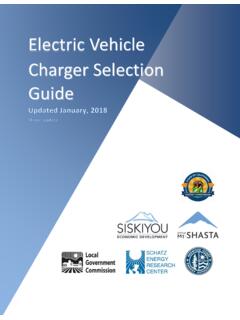
8 If the Solo was built earlier than January 2019, Type B RCD protection should be fitted; the symbols printed on the RCD in Fig. 2 can be used to identify the type of RCD should be taken if using pollution degree 2 devices if located outside. Fig. 2 RCD Markings Type A Type B The RCD may include additional : A vehicle DC leakage fault can blind certain type AC Protection Devices (SPDs):See BS7671: section 443 Solo 3 includes Type 3 protection against transient over voltages (+/-2kV Line-Earth and +/-1kV Line-Line as a requirement of EN 61000-6-1). The guidance on risk calculation in section in most cases is difficult and it may be prudent that Type 2 protection should be installed at the source of supply, especially if life support equipment or business operations could be affected.
9 Type 1 SPD may also be desired in certain higher risk locations. Notes: EU homologated battery electric vehicles do not have the ability to create AC supply voltage spikes under normal circumstances. SPDs have a finite life expectancy and may require replacement in as little as 1 year. Frequent checks of the SPDs health indicator is advised. Solo 3 - HomeSolo 3 - Domestic PP-D-210079-2 Install Guide S3-UK-H-IG
10 Transformers If a galvanically isolated transformer is required, it should be placed upstream of the evse . The Neutral output feed of the transformer shall be connected to evse earth (creating a TN-S system). The PE taken before any RCD and MCB (if 2 pole MCB is used), resistance measured between the evse earth and PE Earth must be less than 100 ohms. Do not connect the output earth/neutral of the transformer to a PME earthed system. Upstream transformer RCD protection may be of Type AC (if fitted) so downstream RCD protection is still should be rated for 100% duty cycle at 10% above rated charge current.