Transcription of PQ-Proportional Valves with integrated Electronics …
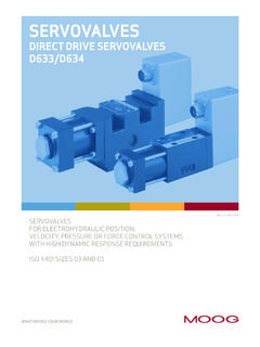
1 1PQ- proportional Valveswith integrated ElectronicsD691 SeriesISO 4401 Size 052D691 SeriesProportional Control PQ-ValvesTwo stage withThis catalogue is for users withtechnical knowledge. To ensurethat all necessary characteristicsfor function and safety of thesystem are given, the user has tocheck the suitability of theproducts described case of doubt please quality management systemis certified in accordance withDIN EN ISO PQ-ValveD691 SeriesOperational features Considerably improved flow recovery (more than 90% ofthe pilot stage internal leakage flow) contributes to energysaving, especially for machines with multiple Valves . Improved dynamics due to high natural frequency.(500 Hz) of the ServoJet pilot stage. Reliable operation. The high pressure recovery of the ServoJetstage (more than 80 % hp at 100 % command signal) provideshigher spool driving forces and ensures enhanced spool positionrepeatability.
2 Operational with only 15 bar pilot pressure. with this arobust proportional control valve for low pressure systems isavailable. The pilot stage filter has almost unlimited life due to the200 m nominal fineness. Improved frequency response allows high spool positionloop gain. The high loop gain provides excellent static anddynamic response, resulting in superior control systemperformance. Fail-safe version with defined safe spool position using aspring, a poppet valve or by external supply cut proportional control PQ- Valves D691 series are dualfunction Valves for 2x2-, 3-, 4- and5-way PQ- Valves modulate a fluidflow and control in closed loopa pressure (upper or lowerpressure limit). The Valves aresuitable for pressure control andpressure limiting control Electronics for thespool position and pressure loopsand a pressure transducer areintegrated in the over 15 years MOOG hasbuilt PQ- Valves with integratedelectronics.
3 During this timemore than 30 000 PQ-Valveshave been delivered andsuccessfully applied to injectionmolding, heavy industry, pressesand paper processing. The val-ves have proved to be reliableespecially when high dynamicperformance is Valves have been continuallydeveloped. with MOOG s newServoJet pilot stage a furtherstep has been taken in thedirection of energy saving pilot stage uses the jet pipeprinciple which for over 8 yearshas been operating reliably indifferent MOOG integrated valve electronicsrequire either 24 Volt DC or a 15 Volt DC power valve seriesdescribed in thiscatalogue have suc-cessfully passed EMC testsrequired by EC Directive. Pleasetake notice of the respectivereferences in the T A P B T2 Y3 Flow rate and pressure dropThe actual flow is dependentupon electrical command signaland valve pressure drop.
4 Theflow for a given valve pressuredrop can be calculated using thesquare root function for sharpedged orifices as follows:Flow rate modeAn electrical command signal(flow rate set point) is applied tothe integrated position controllerwhich drives the valve coil. Theposition transducer (LVDT) whichis excited via an oscillatormeasures the position of thespool (actual value, positionvoltage).This signal is then demodulatedand fed back to the controllerwhere it is compared with thecommand signal. The controllerdrives the pilot valve until theerror between command signaland feedback signal is zero. Thusthe position of the spool is pro-portional to the electrical com-mand [l/min] = calculated flowQN[l/min] =rated flowhp [bar] = actual valve pressuredrophpN[bar] = rated valve pressuredropQQppNN= Pressure control modeThe afore mentioned flow ratecontrol is superimposed with apressure limiting control.
5 Bothcommand signals (external flowcommand signal and limitingpressure command signal) mustalways be difference between externalflow command signal and outputsignal of the pressure limitingcontroller results in a spoolposition command signal. Thisoutput signal is zero as long as theactual pressure is smaller than thelimiting pressure command the actual pressure valueexceeds the limiting pressurecommand value, the pressurelimiting controller reduces thespool position command signaluntil the actual pressure valueequals the limiting pressurecommand instead of pressure limiting apressure control has to beinstalled, the external flowcommand signal must beselected that high, so that thelimiting function actually is necessary because thepressure limiting controller canonly reduce the spool positioncommand.
6 The external flowcommand signal should belarger than 30 % of rated signal(see diagrams on page 4).External pilot pressureIf large flow rates with high valvepressure drop are required anappropriate higher pilot pressurehas to be chosen to overcomethe flow forces. An approximatevalue can be calculated asfollows:Q [l/min] = max. flowhp [bar] = valve pressure dropwith QAK[cm2] = spool drive areapX[bar] = pilot pressureThe pilot pressure pX has to be atleast 15 bar above the returnpressure of the pilot 17 102, 4D691 SeriesTypical characteristic curvesFlow and pressure responseFlow step responseFrequency response (flow)Pressure step responseExamples for pressure step response showthe effect of valve flow setting and entrap-ped fluid volume on pressure controldynamics. Valve type withoptimized PID pressure limiting controllerat operating pressure pP = 250 and measured with entrapped fluid volumeof 1000 cm.
7 Valve flow command 80 % of response data measured at 140 bar pilotpressure, fluid viscosity of 32 mm /s and fluidtemperature of 40 vs. signal curveat hpN = 5 bar per landSpool B: ~critical lap, linear characteristicSpool U: ~critical lap, curvilinear characteristic(5-way only)Spool T: ~20 % overlap, linear characteristicOptimised and measured with entrapped fluid volumeof 1000 cm .Valve flow command 10 / 25 / 80 % of for entrapped fluid volume of 1000 cm butmeasured with 5000 flow command 80 % of and measured with entrapped fluid volumeof 5000 cm .Valve flow command 80 % of : It is necessary to adapt the valvep- Electronics to the load conditions for anynew application. If required please contactMOOG for SeriesApplication notes3-way valve in main line5-way valve in main line4-way valve in main line2x2-way valve in by-pass line(bleed off)only with X and Y externalP and T ports interchanged,not conforming to ISO 4401optional: X and Y externaloptional: Y externaloptional:Y externalThe device operates as a 3-waypressure reducing valve withflow from P A or A 2T.
8 Onlyone load port (A) is device operates like the 3-way PQ-Valve but with doubledflow rate into the load. Adirectional change of the loadmotion requires an shuttle device operates from P Alike a 3-way PQ-Valve. In theopposite direction P B it allowsonly flow modulation. By thismeans the direction of loadmotion can be reversed (openloop velocity control for loadretract).Venting of pressure transducerBefore first operation of thevalve the internal lines of thepressure transducer must becarefully selecting the installationposition of the valve care mustbe taken that the bleeding screwcan become the load is located higher thanthe PQ-Valve the load also mustbe vented at its highest : Vent only at reducedpressure! Danger of injury! with shuttle device operates as anelectrically adjustable 4-waythrottle valve, i.
9 E. the load canbe operated with pressurecontrol in both directions one of the load ports ispressure controlled. The shuttlevalve transmits the driving(higher) load pressure to thesingle pressure transducer. Anelectronic logic circuit providesfor the coordination of motiondirection and pressure controldepending on the polarity of theflow rate command signal. Theother port is more or less opento tank line which is provided bythe special spool land spring centered fail-safeversion requires external pilotsupply port X to be device has parallel flowpathes and operates as elec-trically adjustable pressure reliefvalve from A T and B T2, res-pectively. At zero commandsignal the valve is fully open,i. e. the pressure in the loadports is zero apart from minorpres-sure build up due to linelosses.
10 A minimum pilot pressure(pX > 15 bar) has to be can be achieved by a checkvalve with 15 bar crackingpressure (as shown) or by aseparate pilot supply SeriesValve Electronics withsupply voltage 24 VoltCommand signal for flow QVoltage command 0 to 10 VThe spool stroke of the valve isproportional to (U4 U2). 100 %valve opening P 2A und B 2T isachieved at +10 V input signal. At0 V command the spool is in acentred command 0 to 10 mA(4 to 20 mA resp.)The spool stroke of the valve isproportional to I4 (I4-12 mA resp.).100 % valve opening P 2A andB 2T is achieved at +10 mA(20 mA resp.) input signal. At0 mA (12 mA resp.) commandthe spool is in a centred value spool position (Q) Valves with voltage andcurrent command inputThe actual value, i. e. the spoolposition, can be measured be-tween pins 6 and 7.