Transcription of PRACTICAL ANTENNA DESIGN - N5DUX homepage
1 1 PRACTICAL ANTENNA DESIGN 140-150 MHZ VHF TRANSCEIVERS Online Edition 2 PRACTICAL ANTENNA DESIGN 140-150 MHZ VHF TRANSCEIVERS Online Edition ELPIDIO LATORILLA LEDF Media 3 Published by LEDF Media. COPYRIGHT, 2000 by Elpidio Latorilla First Year of Publication, 2000 All rights reserved. No part of this book may be reproduced in any form or by any means, except brief quotations for a review without permission in writing from the Author. 4 DEDICATION This book is sincerely dedicated to the memories of Ricardo, Mimi, Nida and Poloy who through their examples taught me how to be responsible, strong and steadfast for what one aspires for. To them I give my deepest respect. They died but their ideals will 5 TABLE OF CONTENTS 1 2 3 4 5 6 7 8 9 10 11 12 13 14 15 16 17 18 19 GROUNDPLANE ANTENNA Model GROUNDPLANE ANTENNA Model GROUNDPLANE ANTENNA Model J-FED HALFWAVE ANTENNA Model coaxial DIPOLE Model DIPOLE ANTENNA (gamma fed)
2 Model QUAD LOOP ANTENNA Model DISCONE ANTENNA Model DISCONE ANTENNA Model DISCONE ANTENNA Model 5/8 WAVE ANTENNA Model 5/8 WAVE ANTENNA Model 5/8 WAVE ANTENNA Model COLLINEAR ANTENNA Model STACKED DIPOLE ARRAY Model YAGI-UDA ANTENNA Model MULTI-ELEMENT YAGI-UDA ANTENNA STACKING YAGI FORMULAS FOR CONVERTING ANTENNA DESIGNS FOR OTHER FREQUENCY ANSWERS TO REVIEW GLOSSARY OF ANTENNA 6 7 15 26 36 48 60 75 85 99 105 116 131 139 151 158 162 169 172 175 186 194 196 200 6 INTRODUCTION This book is one of a series designed to help anyone who wants to construct antennas for radio transceivers but who has only a basic knowledge in radio-communications technology. The approach applied in this book is similar to the do-it-yourself methods of trade books and theories are kept to a minimum. Detailed illustrations are extensively used throughout the whole process of ANTENNA construction to simplify the otherwise difficult to comprehend technical jargon.
3 The ANTENNA designs presented here are specifically cut to the dimensions necessary for proper operation in 140-150 MHz VHF band. Each chapter deals with a particular DESIGN and an extra chapter at the last part is added to help the constructor in converting the given ANTENNA dimensions for other frequencies. However, the formulas for conversion give only a generalized information and much of the fine-tuning of the new dimensions is left to the actual experimentation of the constructor. A highly detailed no-guessing ANTENNA dimensions for other frequency bands are described in other books in this series written by the author. The choice of a certain DESIGN for a particular application is left to the decision of the constructor. In selecting a DESIGN , certain factors like portability, ruggedness, compactness, signal gain versus size, weight, wind loading and availability of materials must be taken into account to realize an optimum performance from a particular ANTENNA .
4 The author assumes that the interested constructor has already some experience in basic construction techniques related to radiocommunications equipment installation like soldering VHF connectors to coaxial cables, making a pig tail, cutting aluminum tubes and using an SWR meter. Obviously a knowledge in operating a VHF transceiver is the most important. Here is one rule of a thumb in installing VHF antennas: If you use an RG-58/U coaxial cable to feed the ANTENNA , do not use more than 20 meters or 60 feet long. More than this length, much of the signal (almost half) is lost in the cable and will substantially degrade your ANTENNA 's performance. If it is unavoidable to extend this length, use the larger RG-8/U cable instead. Although this cable is about four times more expensive than RG-58/U cable, this is the only way you can avoid signal losses in the cable. It is the author's hope that this book will provide adequate information to anyone wishing to build his own antennas for VHF tranceivers.
5 7 1 GROUNDPLANE ANTENNA Model FA-2 Reliable communications in radio systems depends upon the over-all effectiveness of both the base station and mobile unit antennas. The radiation pattern of the transmitted signal is extremely important since it must be transmitted and received in densely populated areas as well as over long distances. If you are situated in the center of a town or a city, omnidirectional pattern is best suited for you. Omni-pattern is also the best choice when you do not know the exact direction or location of the station you are communicating with. Directive pattern is PRACTICAL only if you know exactly which direction must the signal be beamed to, in order to maximize the transfer of RF energy. However, antennas with directive patterns are more complex in DESIGN and will be discussed in later chapters.
6 Generally, antennas for VHF bands are mounted as high off the ground as PRACTICAL to overcome the limitations of the so called line-of-sight transmission and reception. An artificial ground must then be used since the ANTENNA is well above the ground in this case. This is not a problem in automobiles since this artificial ground is provided by either the metal roof or body of the car. For tower installations however, some means must be provided to simulate this artificial ground. This is accomplished by the groundplane radials which are usually made of thin metal rods or tubes each cut to quarterwavelength long and mounted at the base of the ANTENNA . The rods sometimes bend downward at an angle of about 45 degrees below the horizontal. This angle is important to maintain the correct impedance match of the system. 8 The ease of construction and low cost of a groundplane ANTENNA makes it an ideal choice for VHF operators.
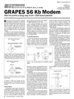
7 The unit described in this chapter uses bronze rods for the radiating element because of their availability and a bronze rod is the easiest to connect to the center pin of the coaxial connector. The groundplane radials are made of cheaper aluminum tubes. Obviously, the ANTENNA is not easy to disassemble once completed so its use is commonly confined to fixed installations requiring little maintenance. The operational frequency bandwidth of FA-2 is from 140 MHz up to 150 MHz exhibiting an SWR response of less than :1 over the entire bandwidth. It has a gain of 1 dB (unity gain) compared to a real dipole. Its signal pattern is omni-directional. Figure Groundplane ANTENNA Model FA-2. Materials List Quantity Specification/Description Dimensions 4 Aluminum Tubes 3/8 id x 20'' each 1 Brass Rod - the brass rod for 1/8'' diameter acetylene welding is recommended 1 SO-239 VHF female connector without flange 8 Stove bolts - brass or stainless 1/8'' x 3/4'' 8 Lockwashers - brass,stainless or GI 1/8'' id 8 Hex nuts - brass.
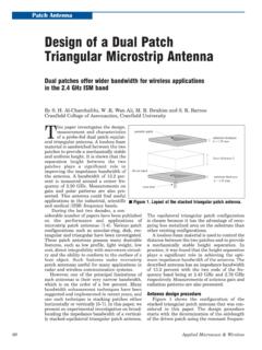
8 Stainless or GI 1/8'' id 1 Aluminum plate gauge 14 or 16 2'' x 6'' 2 U-bolts with accompanying hex nuts and lockwashers *id - inside diameter 9 Construction First of all construct the ANTENNA mount. It is made from a 1/8'' thick aluminum plate cut to 2'' x 6''. Drill a hole in the plate big enough for the SO-239 VHF connector to insert into (about 5/8'' or mm). Drill the hole at the point about 1" away from one end (see Figure ). Figure ANTENNA mount and hole Dimensions. Next drill four holes at the other end of the plate following Figure for the proper dimensions. Make sure that the distance between one pair of holes perpendicular to the length of the metal sheet must be the same with the distance of both ends of the U-bolt that will be inserted into it.
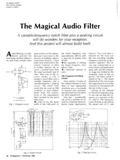
9 Figure Hole dimensions for the U-bolts. 10 Next, drill eight holes (1/8" diameter) around the large hole following Figure for the proper dimensions. Figure Hole dimensions for the radial elements around large hole. Bend the aluminum plate down to a 90 angle (see Figure ). Follow the illustration for the exact point to bend. Figure Bending the aluminum mounting plate. 11 Insert the SO-239 VHF connector facing downwards into the mounting plate and fix it permanently with its nut (see Figure ). Discard the grounding ring/lug. Figure Mounting the SO-239 into the plate. Cut the brass rod to a length of 19" ( cm) and insert one of its end into the center pin of the SO-239 connector (see Figure ). The brass rod may or may not fit into the center pin immediately, so you may need to file away a small portion at the end of the rod to reduce it to a smaller diameter.
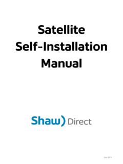
10 Figure Preparing one end of the brass rod to fit inside the SO-239. 12 Cut four aluminum tubes to a length of 20" each and drill two holes (1/8 " diameter) at one end (see Figure ). Figure Preparing the tubes. Bend the aluminum tubes to a 45 degree angle at the point 1 inch away for the end with two holes. The direction of the bend must be parallel with the axis of the drilled hole (see Figure ). Figure Bending the tubes. 13 Mount the four aluminum tubes into the angled plate by bolting each element with 1/8" x 3/4" stove bolts (see Figure ). The stove bolts must be made of rust resistant material such as stainless steel, brass or GI. Figure Mounting the tubes on the metal plate. 14 Finally , you can mount the ANTENNA to the mast using the two U-bolts . Figure Mounting the ANTENNA to the mast. 15 2 GROUNDPLANE ANTENNA Model FQ-2 The ANTENNA model FQ-2 is a development from the basic configuration of a groundplane.