Transcription of Practical Design to Eurocode 2
1 Autumn 2016 TCC's Eurocode 2 Webinar course: lecture 41 Practical Design to Eurocode 2 The webinar will start at 414thOctober 2015 Autumn 2016 TCC's Eurocode 2 Webinar course: lecture 42 Week 3 Model Answers to Cover = 35 mm to each facefck= 30 MPaDesign the beam in flexure and shearGk= 10 kN/m, Qk= kN/m (Use EC0 eq. ) 8 m300450 Beam Exercise Flexure & ShearAutumn 2016 TCC's Eurocode 2 Webinar course: lecture 43 Exp ( ) Remember this from the first week? Aide memoireOrConcise Table :- Load, Mult, d, K, K , (z/d,) z, As, VEd, Asw/s mmArea, 2016 TCC's Eurocode 2 Webinar course: lecture 44 Solution - FlexureULS load per m= (10 x + x ) = kN/mMult= x 82/8= 186 kNmd= 450 - 35 - 10 32/2 = 389 mm1370303893001018626ck2. fbdMKK<K No compression reinforcement required 26ydsmm1280334x43510x186 zfMAProvide 3 H25 (1470 mm2)K = - ShearShear force, VEd= x 8 /2 = 93 kNShear stress:vEd= VEd/( ) = 93 x 103/(300 x x 389)= MPavRd= MPavRd> vEd cot = vEdbw/(fywdcot )Asw/s= x 300 /(435 x )Asw/s= mmTry H8 links with 2 legs, Asw= 101 mm2s < 101 = 420 mm Maximum spacing = d= x 389 = 292 mm provide H8 links at 275 mm spacingAutumn 2016 TCC's Eurocode 2 Webinar course: lecture 45 AnalysisLecture 412thOctober 2016 Summary: Lecture 4EN 1992-1-1: Section 5 Structural Analysis: Section General Section Geometric Imperfections Section Idealisation Sections & Linear Elastic Analysis Section Plastic Analysis Section Strut & Tie Worked Example Using Strut & Tie Sections to - outline ExercisesAutumn 2016 TCC's Eurocode 2 Webinar course: lecture 46 Section GeneralStructural Analysis( ) Common idealisations used.
2 Linear elastic behaviour linear elastic behaviour with limited redistribution plastic behaviour non-linear behaviour Local analyses are required where linear strain distribution is not valid: In the vicinity of supports Local to concentrated loads In beam/column intersections In anchorage zones At changes in cross sectionAutumn 2016 TCC's Eurocode 2 Webinar course: lecture 47 Soil/Structure Interaction( ) Where soil/structure interaction has a significant affect on the structure use EN 1997-1 Simplifications (see Annex G) include: flexible superstructure rigid superstructure; settlements lie in a plane foundation system or supporting ground assumed to be rigid Relative stiffness between the structural system and the ground > indicate rigid structural system Second Order Effects( ) For buildings 2ndorder effects may be ignored if they are less than 10% of the corresponding 1storder effects. (But of course you first need to know how big they are!)( For 2ndorder effects with axial loads, (columns), two alternative methods of analysis are permitted: Method A based on nominal stiffnesses ( ) Method B based on nominal curvature ( )Autumn 2016 TCC's Eurocode 2 Webinar course: lecture 48 Section Geometric ImperfectionsGeometric Imperfections ( ) Deviations in cross-section dimensions are normally taken into account in the material factors and should not be included in structural analysis Imperfections need not be considered for SLS Out-of-plumb imperfection is represented by an inclination, iwhere i= 0 h m where 0 = 1/200 h = 2/ l; 2/3 h 1 m = (0,5(1+1/m)l is the height of member (m) m is the number of vert.))
3 MembersAutumn 2016 TCC's Eurocode 2 Webinar course: lecture 49a) as an eccentricity, ei, whereei= il0/2 So for walls and isolated columns ei= l0/400, b) as a transverse force, Hi, whereHi = iNfor unbraced membersHi= 2 iNfor braced membersThe effect of geometric imperfections in isolated members may be accounted for in one of two different ways: either:orGeometric Imperfections ( )UnbracedBraceda) & b) (cont)eiand Hiin isolated members( )Most usualGeometric Imperfections ( )Autumn 2016 TCC's Eurocode 2 Webinar course: lecture 410 NaNbHili i NaNbHi/2i /2i Bracing SystemFloor DiaphragmRoofHi = i(Nb-Na)Hi = i(Nb+Na)/2Hi = iNab) (cont)Hiin structural systemsGeometric Imperfections ( )b) (cont)Partial factors for HiIt is not clear how the notional force Hishould be regarded, as a permanent action, a variable action, an accidental action. However by inference if should be the same as for the constituent axial loads N, NEd, Naand/or Nb. Hi= ( + )/(Gk+ Qk)But TCC s Worked Examples says As Hiderives mainly from permanent actions its resulting effects are considered as being a permanent action too.
4 And Hi= G= was Imperfections ( )Autumn 2016 TCC's Eurocode 2 Webinar course: lecture 411 Section Idealisation Beam: Span 3h otherwise it is a deep beam Slab: Minimum panel dimension 5h One-way spanning Column: h 4b and L 3h otherwise it should be considered as a wall Ribbed or waffle slabs need not be treated as discrete elements provided that: rib spacing 1500mm rib depth below flange 4b flange depth 1/10 clear distance between ribs or 50mm - transverse ribs are provided with a clear spacing 10 hIdealisation of the structure ( )As week 2 Autumn 2016 TCC's Eurocode 2 Webinar course: lecture 412bb1b1b2b2bwbwbeff,1beff,2beffbeff= beff,i+ bw bwhere beff,i= 0,2bi+ 0,1l0 0,2l0 and beff,i bil3l1l20,15(l1+ l2 )l =0l0= 0,7 l2l0= 0,15 l2 + l3l0= 0,85 l1l0, is the distance between points of zero moment , viz:Effective Flange Width( )As week 2leff= ln+ a1+ a2 The Design moment and reaction for monolithic support should generally be taken as the greater of the elastic and redistributed values Critical Design moment usually at face of support.
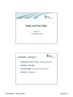
5 ( 0,65 the full fixed moment). leffailnhtlnleffa = min {1/2h; 1/2t }i Permitted reduction, MEd= Length of Beam or Slab( )As week 2 Autumn 2016 TCC's Eurocode 2 Webinar course: lecture 413 Sections & Linear Elastic Analysis Linear elastic analysis may be carried assuming: uncracked sections (concrete section only) linear stress-strain relationships mean value of the modulus of elasticity Linear elastic analysis may be used for both ULS and SLS For thermal deformation, settlement and shrinkage effects at ULS a reduced stiffness corresponding to cracked sections may be Elastic Analysis( )Autumn 2016 TCC's Eurocode 2 Webinar course: lecture 414 In continuous beams or slabs which are mainly subject to flexure and for which the ratio of adjacent spans is between 0,5 and 2 0,4 + (0,6 + 0,0014/ cu2)xu/d 0,7 for Class B and C reinforcement 0,8 for Class A reinforcementwhere: is (redistributed moment)/(elastic moment)xuis the neutral axis depth after redistribution For column Design the elastic values from the frame analysis should be used (not the redistributed values).
6 Linear Elastic Analysis with Limited Redistribution ( ) redistfck =70fck =60fck =50 Redistribution Limits redistfck =70fck =60fck =50for Class B & C Steelfor Class A SteelAutumn 2016 TCC's Eurocode 2 Webinar course: lecture 415lx(> ly)ly ly/4ly/4ly/4ly/4= lx- ly/2= ly/2= ly/2 A B B A Column stripB Middle strip Negative moments Positive moments Column Strip 60 - 80% 50 - 70% Middle Strip 40 - 20% 50 - 30% Note: Total negative and positive moments to be resisted by the column and middle strips together should always add up to 100%. Flat Slabs: Annex IThe division of Flat Slabs into Column strips and Middle strips is dealt with in Annex I, under Equivalent Frame Analysis As week Plastic AnalysisAutumn 2016 TCC's Eurocode 2 Webinar course: lecture 416 Plastic analysis requires ductility which is provided if: xu/d for C50/60 (or xu/d for C55/67) ( K )and Class B or C reinforcement usedand < Msppt/ Mspan< ) Plastic analysis may be used for ULS For higher strengths check rotation capacity to Analysis( )Yield Line MethodBased on the work method External energy Expended by the displacement of loadsInternal energy Dissipated by the yield lines rotating=m m m m Plastic Analysis : Yield Linem m mxyAutumn 2016 TCC's Eurocode 2 Webinar course: lecture 417+10%Plastic Analysis : Yield Line & Flat SlabsUpper bound (correct or unsafe) so.
7 Strut and Tie Autumn 2016 TCC's Eurocode 2 Webinar course: lecture 418 What is strut and tie?Strut-and-tie models (STM) are trusses consisting of struts, ties and ) ModellingImagine or draw stress paths which show the elastic flow of forces through the structureb) STMR eplace stress paths with polygons of forces to provide deep beamConventionally, struts are drawn as dashed lines, ties as full lines and nodes numbered. What is strut and tie?37c) Design members Design ties Check nodes and struts (may be)d) IterateMinimise strain energy (minimise length of ties)A deep beamAutumn 2016 TCC's Eurocode 2 Webinar course: lecture 419 What is strut and tie?Strut and tie models are based on the lower bound theorem of plasticity which states that any distribution of stresses resisting an applied load is safe providing: Equilibriumis maintainedand Stresses do not exceed yield What is strut and tie?In strut and tie models trusses are used with the following components: Struts (concrete) Ties (reinforcement) Nodes (intersections of struts and ties) Eurocode 2 gives guidance for each of principle - where non-linear strain distribution exists, strut and tie models may be used.
8 Supports Concentrated loads OpeningsAutumn 2016 TCC's Eurocode 2 Webinar course: lecture 420 What is Strut and Tie?A structure can be divided into: B (or beam or Bernoulli) regions in which plane sections remain plane and Design is based on normal beam theory,and D (or disturbed) regions in which plane sections do not remain plane; so normal beam theory may be considered inappropriate and Strut & Tie may be regionsP1P2 Poll: At failure, what is P2/ P1?Concept by R Whittle, drawn byI Feltham. Used with permissionPlease answer:a) P2 P1 b) P2 P1 c) P2 P1 d) P2 P1e) P2 P1 f) P2 P1 Autumn 2016 TCC's Eurocode 2 Webinar course: lecture 421 StrutsCross-sectional dimensions of the strut are determined by dimensions of the nodes and assumptions made its thickness x dimension a ( see Figures}The stress in struts is rarely critical but the stress where struts abut nodes is (see later).However .. StrutsWhere there is no transverse tension Rd,max= fcd= fckOtherwise, where there is transverse tension Rd,max= fcdWhere: = 1-fck/250 Rd,max= x (1-fck/250) x x (1-fck/250) fckAutumn 2016 TCC's Eurocode 2 Webinar course: lecture 422fccfccfctfctTransverse tensionBi-axial Strength of ConcreteAxial stress xTransverse stress, y, o r zTensionCompressionTensionCompressionLos s in axial strength due to transverse Ties/Discontinuities in strutsAreas of non-linear strain distribution are referred to as discontinuities Partial discontinuityFull discontinuityCurved compression trajectories lead to tensile forcesAutumn 2016 TCC's Eurocode 2 Webinar course.
9 Lecture 423 Partial discontinuityTension in the reinforcement is TWhen b H/2T= [(b a)/b] FReinforcement ties to resistthe transverse force T may be discrete or can be smeared over the length of tension zone arising from the compressionstress trajectoriesTTFull discontinuityWhen b > H/2T= (1 ) FReinforcement ties to resist the transverse force T may be discrete or can be smeared over the length of tension zone arising from the compression stress trajectoriesTTAutumn 2016 TCC's Eurocode 2 Webinar course: lecture NodesNodes are typically classified as:CCC Three compressive strutsCCT Two compressive struts and one tieCTT One compressive strut and two tiesCCC nodesThe maximum stress at the edge of the node: Rd,max= k1 fcdWhere:k1= = 1-fck/250 Rd,max= (1-fck/250) x x (1-fck/250) fckNB Hydrostatic pressures: the stresses c0, Rd,1 Rd,2 & Rd,2etc are all the 2016 TCC's Eurocode 2 Webinar course: lecture 425 CCT nodesThe maximum compressive stress is: Rd,max= k2 fcdWhere:k2= = 1-fck/250 Rd,max= (1-fck/250) x x (1-fck/250) fck(stresses in the two struts should be equal)CTT nodesThe maximum compressive stress is: Rd,max= k3 fcdWhere:k3= = 1-fck/250 Rd,max= (1-fck/250) x x (1-fck/250) fckAutumn 2016 TCC's Eurocode 2 Webinar course: lecture 426 TiesDesign strength, fyd= should be anchored into nodesThe anchorage may start as the bar enters the strutConstruction of an STM for a deep beam using the load path methodUsually taken as a maximum of 1:263oAutumn 2016 TCC's Eurocode 2 Webinar course: lecture 427 Strut & Tie Models Similarity (single point load)Worked ExamplePile-Cap Using S&T Autumn 2016 TCC's Eurocode 2 Webinar course.
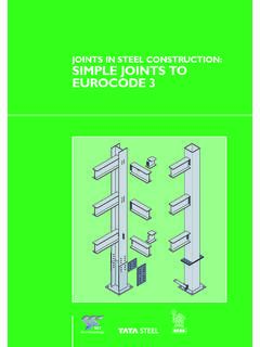
10 Lecture 428 Pile-cap exampleUsing a strut and tie model, what tension reinforcement is required for a pile cap supporting a 500 mm square column carrying 2500 kN (ULS), and itself supported by two-piles of 600 mm diameter. fck= 30 MPa2 500 kN (ULS)27001400150 Breadth = 900 mmPile-cap exampleAngle of strut = tan-1(900/1300)= Width of strut*= 250/cos = 304*mmForce per strut = 1250/cos = 1520 kNForce in tie= 1250 tan = 866 kN2 500 kN (ULS)180014001 250 kN (ULS)100 Strut angle500/2 = 2501 250 kN (ULS) kNSTM*Conventional but simplistic - see laterAutumn 2016 TCC's Eurocode 2 Webinar course: lecture 429 Pile-cap exampleUsually that is probably as far as you would go. But for the sake of completeness and the exercise you will be undertaking we will continue:5H25 Area of steel required:As 866 x 103/435 1991 mm2 Use 5 H25s (2455 mm2)Pile-cap exampleCheck forces in trussStress in strut(top under half of column) =1520 x 103/(304 x 500) Ed= MPaStrength of strut: Rd,max= (1-fck/250) fck= MPaOK866 kNAutumn 2016 TCC's Eurocode 2 Webinar course: lecture 430 Pile-cap exampleNodes: topFrom before Ed,2= MPa (from above) Ed,3= MPa (as above) Ed,1= 2500 x 103/(5002)= MPa Rd,max(for CCC node)= (1-fck/250) fck= MPa612500 kN1520 kN1520 kN2500 kN1520 kN1520 kN(Upside down elevation!)