Transcription of Practical Manual 2017-2018 On Embedded Systems
1 ( ) Semester IV Embedded Systems Practical Manual 2017 - 2018 1 Practical Manual 2017 - 2018 On Embedded Systems (Course Code-USIT4P5) For (Semester IV) Prepared By Bhide ,Ghatkopar. ( ) Semester IV Embedded Systems Practical Manual 2017 - 2018 2 Index Sr No Title Introduction Introduction to Embedded system Practical Introduction to 8051 Microcontroller Introduction to TKBase Trainer kit List of Practical 1. Design and develop a reprogrammable Embedded computer using 8051 microcontrollers and to show the following aspects.
2 A. Programming b. Execution c. Debugging 2. a Configure timer control registers of 8051 and develop a program to generate given time delay. b To demonstrate use of general purpose port Input/ output port of two controllers for data transfer between them. 3. a Port I / O: Use one of the four ports of 8051 for O/P interfaced to eight LED s. Simulate binary counter (8 bit) on LED s b To interface 8 LEDs at Input-output port and create different patterns. c To demonstrate timer working in timer mode and blink LED without using any loop delay routine.
3 4. a Serial I / O: Configure 8051 serial port for asynchronous serial communication with serial port of PC exchange text messages to PC and display on PC screen. Signify end of message by carriage return. b To demonstrate interfacing of seven-segment LED display and generate counting from 0 to 99 with fixed time delay. 4. c Interface 8051 with D/A converter and generate square wave of given frequency on oscilloscope. 5. a Interface 8051 with D/A converter and generate triangular wave of given frequency on oscilloscope b Using D/A converter generate sine wave on oscilloscope with the help of lookup table stored in data area of 8051 .
4 6. Interface stepper motor with 8051 and write a program to move the motor through a given angle in clock wise or counter clock wise direction 7. Generate traffic signal. 8. Implement temperature control. 9. Implement Elevator control. 10. a To demonstrate the procedure for flash programming for reprogrammable Embedded system board using Flash Magic b To demonstrate the procedure and connections for multiple controllers programming of same type of controller with same source code in one go, using flash magic. ( ) Semester IV Embedded Systems Practical Manual 2017 - 2018 3 Introduction to Embedded system Practical Embedded system can be defined as a system that has Embedded software and computer hardware which makes it a system dedicated for application(s) or a specific part of an application.
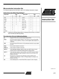
5 Constituents of Embedded system hardware Fig 1 Components of Embedded system hardware Processor : Processor has program flow control unit (CU) and execution unit (EU). The CU includes fetch unit for fetching instruction. EU include has circuits that implement the instructions related to data transfer operations and data conversion from one to another. EU also includes ALU and circuits that execute instruction for a program which controls different tasks. system Timers: A timer circuit is configured as a system clock, which generates system interrupts periodically which performs required operation, or it can be configured as Real Time Clock (RTC) that generates system interrupts for schedulers, real time programs.
6 RTC can also be used to obtain software controlled delays. It also functions as driver for software timers. Power Supply, Reset and Oscillator circuit ( ) Semester IV Embedded Systems Practical Manual 2017 - 2018 4 Interrupt handler / controller: Interrupt handling mechanism handles multiple interrupts generated from various processes simultaneously. There can be number of interrupt sources or group of sources. The service to these sources can have priorities according to the system priorities. Certain sources of interrupts are non maskable and cannot be disabled.
7 There is a separate program and data memory for the controller. Internal and external RAM for registers, temporary data and stack, Internal and external ROM for program memory, internal flash memory, memory cards, memory buffers of ports, cache memories. Communication ports: several communication ports serial as well as parallel to communicate with various peripheral devices like keyboards touch screens, sensors, transducers etc. (input) or printers, LED / LCD display, network etc. (output). Power supply, Reset and Oscillator Circuit: Many Embedded Systems have their own power supply; however fee Systems use PC power by connecting to computer.
8 Power supply has range of voltages in one of following range 5 , , 2 and Reset circuit helps the processor to begin processing of instructions from a starting address. This address is set by default in processor Program Counter (PC) on a power up. A program to be executed after reset is - a system program which executes from beginning, or a boot program, or a system initialization program. Reset circuit activates for a fixed period and then deactivates. Software components of Embedded system - An Embedded system processor executes software that is specific to a given application system .
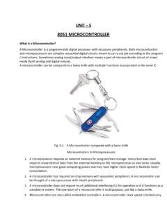
9 Software components include editor, assembler, linker, and loader. The steps involved in executing an Embedded assembly program are as followed 1. An assembler translates the assembly software into machine codes. 2. The code is linked with other required codes. As there are several codes required to linked together for the final binary file. Linker produces binary file. This binary file can directly be run on a computer and is called as an executable file. 3. Loader program performs task of reallocating the codes after finding the physical memory address available at a given instant.
10 The loader is part of operating system and places the codes into its memory after reading the exe file. 4. These codes are to be then located as ROM image. ( ) Semester IV Embedded Systems Practical Manual 2017 - 2018 5 5. Lastly, this ROM image file is either burned into PROM or flash memory using a device programmer tool, or it is masked for the PROM from the ROM image file. Fig 2 Process of converting assembly language program into the machine codes and obtaining the ROM image Software is developed in higher level languages to save efforts instead of using assembly language.