Transcription of Precision Turbine Flowmeters - gasequipment.com
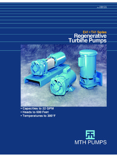
1 Precision Turbine Flowmeters Flowrates: .25 to 12000 GPM Design Applications 35 to 12000 ACFM Liquid and Gas Measurement Temperature Range: -430 to +1000 F Batching C to C. Blending Linear Output Filling High Resolution Process Control Standard and Custom End-fittings SPONSLER, INC. A Unit of IDEX Corporation 2363 Sandifer Blvd. Westminster, SC 29693. (864) 647-2065 op Dr The Sponsler Precision Turbine 150. % VALUE AT RATE OF FLOW. re su Flowmeter measures volume by es Pr a contour mounted Turbine in the Cycles per Ga flow system. The AC signal output llon is detected by a transducer and 100. interpreted by various electronic devices used for flow rate indication nc y and totalization. Sponsler Precision q ue 50 d Fr e Turbine Flowmeters are engineered an CHARACTERISTICS CURVE. ge and manufactured to handle lta Vo problems of viscosity, corrosive media, extreme temperatures, and 0. hazardous materials. The compact, 50 100 150. rugged design has established a new TYPICAL % OF RATED FLOW (GPM).
2 Standard for flow measurement by exceeding the expectations of our industry for higher accuracy and reliability in all operating conditions. TYPICAL K FACTOR (PULSE/GAL). 1 Centistoke Sponsler engineers design flow systems to meet the needs of each customer's application. These processes can be automatic, tistokes semi-automatic, or manual for batch or process control, blending, and 100 Cen filling systems including simple rate indication and totalization. Standard or custom electronic instrumentation TYPICAL VISCOSITY CURVE. is available for a wide range of (1 1/2" Liguid Flowmeter). applications. At Sponsler, we believe that no matter what the application, our commitment to quality and service 0 100. to our customers means that we TYPICAL % OF RATED FLOW (GPM). produce the best flowmeter on the planet. Typical Arrangement of Flowmeter and Readout Instrument SPONSLER, INC. A Unit of IDEX Corporation 2363 Sandifer Blvd. Westminster, SC 29693.
3 (864) 647-2065 Features High pressure applications Custom and standard designs Manufactured in the USA. Interfaces with manual, Material compatible with Wide choice of bearings including semiautomated or completely application carbide for compatability automated systems Pickup Coil: Temperature from -450 F ( C) to 450 F ( C);. Optional to 1000 F ( C). Standard Bearing Choices Materials Of Construction: Include 304 Stainless Steel Stainless Steel Ball 316 Stainless Steel Ceramic Ball (Consult Factory for other materials.). Teflon Sleeve Graphitar Sleeve Carbide Sleeve Fluorosint Sleeve Standard Flow Endfitting Choices: Lightweight Straighteners: Male NPT. Hydraulically Upstream and Downstream Balanced Rotor: 37 Flare for Accuracy 304 Nickel Liquid Rotor Flanged 17-4 PH-SS Rotor High Pressure Tube Fitting Liquids Specifications: (MS-33656), NPT, and ANSI flanges. Others Linearity: +/- available upon request. Premium Linearity: +/- Operating Pressure: Accommodates unlimited (over a specific range) pressure depending on the end-fittings.
4 Repeatability: +/- Calibration: Sponsler Precision Turbine Flowmeters are furnished with stand fluid Premium Repeatability: +/- calibration. Special calibrations available. (over a specific range). Flow Ranges: From .25 to 12,000 GPM. Temperature: -450 F to 450 F. standard with optional 1000 F 17 overlapping ranges standard Temperature: C to C Other Flow Rates available; consult factory standard with optional C. Note: Specifications based on ball bearings. Materials: Sponsler Precision Turbine Altering ball bearing selection may alter Flowmeters are constructed of 300 and 400 series specifications performance. Consult factory stainless steel. A variety of other materials are for changes in specifications. available to satisfy most applications including CPVC, Teflon, and Kynar for corrosive materials. Electrical Output: A minimum of 30 mV peak to peak at the minimum of repeatable flow. Pressure Drop: 4 psi at nominal rated flow range End-Fittings: AN series of 37 , flare tube Sizing Chart Liquids GPM / LPM.
5 Size Minimum Minimum Nominal Extended Approx. Repeatable Linear Maximum Maximum K Factor 1/4 / 1 / 2 / 10 3 / 11 15000. 3/8 / 1 / 3 5 / 19 / 28 3160. 1/2 / 2 / 5 / 36 12 / 45 3160. 5/8 / 3 / 7 16 / 61 18 / 68 1875. 3/4 / 7 / 10 29 / 110 35 / 132 1035. 1 3 / 11 4 / 15 60 / 227 75 / 284 500. 1 1/4 4 / 15 6 / 23 93 / 352 115 / 435 322. 1 1/2 6 / 23 8 / 30 130 / 492 175 / 662 230. 2 12 / 45 15 / 57 225 / 852 275 / 1041 133. 2 1/2 15 / 57 25 / 95 400 / 1514 500 / 1893 75. 3 30 / 114 40 / 151 650 / 2461 800 / 3028 4 50 / 189 75 / 284 1250 / 4732 1500 / 5678 5 100 / 379 140 / 530 2000 / 7571 2500 / 9464 6 125 / 473 200 / 757 2900 / 10978 3600 / 13627 8 280 / 1060 330 / 1249 5200 / 19684 6400 / 24227 10 550 / 2082 650 / 2461 8000/ 30283 9800 / 37097 12 800 / 3028 900 / 3407 12000 / 45425 15000 / 56781 * Approximate Weight for flanged Flowmeters SPONSLER, INC. A Unit of IDEX Corporation 2363 Sandifer Blvd. Westminster, SC 29693. (864) 647-2065 Gases Sponsler Precision Turbine Gas Flowmeters are designed to measure actual cubic feet or actual volume passing through the flowmeter.
6 Before sizing a flowmeter, it is necessary to convert flow units ( SCFM, LPM, etc.) to actual measured volume. To convert to actual measure volume (ACFM) from standard volume (SCFM), use the following formula: ACFM = SCFM x / Pa x Ta / 530. Whereas: ACFM = actual cubic feet per minute measured gas flow SCFM = standard cubic feet per minute measured gas flow Pa = Operating Pressure in PSIA. (Note: PSIA = PSIG + ). Ta = Temperature in degrees Rankine = F + 460. Specifications: Note: For more information, visit the Application Tools section of our Accuracy of +/- 1% linear website at Repeatability of +/- .25%. or consult factory. Temperature Range -450 F to 450 F standard with optional 1000 F. Temperature Range C to C standard with optional C. Sizing Chart Gas (ACFM / Cubic Meters). Flow Range Extended Flow Range Meter Weight *. Size Minimum Maximum Minimum Maximum Linear Linear Linear Linear LBS / Kg 1/4 / .011 / .10 / .006 / .1 2/1. 3/8 /.
7 02 5 / .14 / .008 10 / .28 2/1. 1/2 / .03 10 / .28 / .02 12 / .34 2/1. 5/8 / .06 20 / .56 / .03 20 / .56 2/1. 3/4 / .07 28 / .80 / .04 35 / .99 4/2. 1 4 / .11 60 / 2 / .06 75 / 5 / 1 1/4 6 / .17 100 / 3 / .08 100 / 7/3. 1 1/2 8 / .23 130 / 5 / .14 150 / 8 / 2 15 / .42 250 / 11 / .31 250 / 13 / 16. 2 1/2 25 / .71 450 / 15 / .42 500 / 18 / 8. 3 40 / 650 / __ __ __ __ 19 / 4 75 / 1200 / 34 __ __ __ __ 36 / 6. 5 150 / 1800 / 51 __ __ __ __ 47 / 21. 6 250 / 2900 / __ __ __ __ 58 / 26. 8 330 / 5000 / __ __ __ __ 119 / 54. 10 650 / 7500 / __ __ __ __ 226 / 103. 12 900 / 12000 / __ __ __ __ 345 / 157. * Approximate Weight for flanged Flowmeters Installation Dimensions End Flanged Flowmeter sizes are based on nominal inside diameter of pipe. Special flanges can usually be provided to specification. For hazardous areas, pickup coils with explosion proof housings can be provided. All Flowmeters 1/2" and smaller will be provided with 1/2" end connections unless otherwise specified.
8 Sizes 1/2" 12". Stainless Steel Unless Otherwise Specified LINE 150# ASA (ANSI) 300# ASA (ANSI) 400# ASA (ANSI) 600# ASA (ANSI) 900# ASA (ANSI) 1500# ASA (ANSI) 2500# ASA (ANSI). SIZE A B A B A B A B A B A B A B. 1/4" 1/2" 5 3 1/2 5 3 3/ 4 5 3 3 /4 5 3 3 /4 7 4 3 /4 7 3. 4 /4 7 5 1/4. * 5/8" 1. 5 /2 3 1/2 5 /2 3 3/ 4. 1 1. 5 /2 3 3 /4 1. 5 /2 3 3 /4 7 4 3 /4 7 3. 4 /4 7 5 1/4. 3/4" 5 1/2 3 7/ 8 5 1/2 4 5/8 5 1/2 4 5/8 5 1/2 4 5 /8 7 5 1/8 7 5 1/8 7 5 1/2. 1" 1. 5 /2 4 1/4 5 1/2 4 7/8 5 1/2 4 7/8 1. 5 /2 4 7/8 8 5 7 /8 8 7. 5 /8 8 6 1/4. 1 1/4" 6 4 5/ 8 6 5 1/4 6 5 1/4 6 5 1/4 8 6 1/4 8 6 1/4 8 7 1/4. 1 1/2" 6 5 6 6 1/8 6 6 1/8 6 6 1/8 9 7 9 7 9 8. 2" 1. 6 /2 6 6 1/2 6 1/2 6 1/2 6 1/2 6 1/2 6 1/2 9 7 9 7 9 8. 2 1/2" 7 7 7 7 1/2 7 7 1/2 7 7 1/2 10 9 5 /8 10 9 5/8 10 10 1/2. 3" 10 7 1/2 10 8 1/4 10 8 1/4 10 8 1/4 10 9 1/2 10 10 1/2 11 12. 3 1/2" 12 8 1/2 12 9 12 9 12 9 - - - - - - 4" 12 9 12 10 12 10 12 10 3/4 12 11 1/2 12 1. 12 /4 12 14. 5" 14 10 14 11 14 11 14 13 14 13 3/4 14 15 1/2 16 19.
9 6" 14 11 14 12 1/2 14 12 1/2 14 14 14 15 14 1. 15 /2 16 19. 8" 16 13 1/2 16 15 16 15 16 16 1/2 16 18 1/2 16 19 18 21 3/4. 10" 20 16 20 17 1/2 20 17 1/2 20 20 20 21 1/2 20 23 22 26 1/2. 12" 24 19 24 20 1/2 24 20 1/2 24 22 24 24 24 1. 26 /2 24 30. * Mates to 1/2" ANSI Flange Typical Flowmeter System Installation Installation Dimensions MS FLARED TUBE Sizes 1/4" 2" ( - cm). APPROX. WT. DIMENSIONS INCHES (CM) END CONNECTIONS INCHES (CM). SIZE INCHES(CM). A B C Flared Tube LBS / Kg 1/4 1/2 ( - cm) 1 1/8 ( cm) 2 9/16 ( cm) 3 ( cm) 3/4 -16 UNJF-3A .38 / .173. 5/8 ( cm) 1 1/8 ( cm) 2 3/4 ( cm) 3 ( cm) 7/8 14 UNJF 3A .75 / .341. 3/4 ( cm) 1 5/8 ( cm) 3 1/4 ( cm) 3 1/2 ( cm) 1 1/16 12 UNJ 3A .75 / .341. 1 ( cm) 1 5/8 ( cm) 3 1/2 ( cm) 4 ( cm) 1 5/16 -12 UNJ-3A / .627. 1 1/4 ( cm) 2 ( cm) 3 7/8 ( cm) 4 3/8 ( cm) 1 5/8 -12 UNJ-3A / .795. 1 1/2 ( cm) 2 1/8 ( cm) 4 3/8 ( cm) 4 5/8 ( cm) 1 7/8 -UNJ-3A / 2 ( cm) 2 3/4 ( cm) 4 3/4 ( cm) 5 3/8 ( cm) 1 1/2 -12 UNJ-3A 3 / MNPT Sizes 1/4 3 ( - cm).
10 APPROX. WT. DIMENSIONS INCHES (CM) END CONNECTIONS INCHES (CM). SIZE INCHES(CM). A B C MNPT LBS / Kg 1/4 1/2 ( - cm) 1 1/8 ( cm) 3 ( cm) 3 ( cm) 1/2 ( cm) .38 / .173. 5/8 ( cm) 1 1/8 ( cm) 3 ( cm) 3 ( cm) 1/2 ( cm) .75 / .341. 3/4 ( cm) 1 5/8 ( cm) 3 1/4 ( cm) 3 1/2 ( cm) 3/4 ( cm) .75 / .341. 1 ( cm) 1 5/8 ( cm) 3 1/2 ( cm) 4 ( cm) 1 ( cm) / .627. 1 1/4 ( cm) 2 ( cm) 3 7/8 ( cm) 4 3/8 ( cm) 1 1/4 ( cm) / .795. 1 1/2 ( cm) 2 1/8 ( cm) 4 3/8 ( cm) 4 5/8 ( cm) 1 1/2 ( cm) / 2 ( cm) 2 3/4 ( cm) 4 3/4 ( cm) 5 3/8 ( cm) 2 ( cm) 3 / 2 1/2 ( cm) 3 1/4 ( cm) 6 1/16 ( cm) 5 3/8 ( cm) 2 1/2 ( cm) / 3 ( cm) 3 1/2 ( cm) 10 ( cm) 5 5/8 ( cm) 3 ( cm) 10 / Model Selection Guide SP (size) (bearing type) (rotor type) (end-fitting) (material) (options). Example: SP 1/4 CB PHL A 4 X. Bearing Type: Rotor Type: End-fitting Type: Material: Options: CB = Cryo Ball NL = 304 Nickel A = NPT 4 = 304SS HT = High Temp. MB = Metal Ball Liquid FA = FNPT * 4L = 304L RF = Mod.