Transcription of Prefabricated Vertical Drains - CeTeau
1 Prefabricated Vertical Drains Technical Design Manual CeTeau stands for innovative ground improvement technologies with Prefabricated Vertical Drains . Prefabricated Vertical Drains (PVD), also called Wick Drains , are Prefabricated drain strips consisting of a polypropylene core extruded into a configuration to transmit a maximum water flow on both sides of the core. The core is wrapped in a non-woven filter, ultrasonically welded at the edges. The CeTeau Vertical Drain System is one of the most widely used drain system in the world, with over 100,000,000 lm installed world wide. This manual serves as a guide to assist engineers with the selection and application of Vertical wick Drains . 2 Prefabricated Vertical Drains Applications and Design Guide THE Vertical WICK DRAIN PRINCIPLE When construction work such as road and airfield embankments, bridge approached, dykes, land reclamation or buildings on soft compressible soils, significant settlements may occur due to consolidation of these soils under the superimposed loads.
2 To avoid serious and potentially expensive problems due to such settlements, it is desirable to cause this consolidation to occur at the outset of project, and in the shortest possible time during the construction period. Consolidation of compressible soils involves removal of pore water from the soil. This is traditionally done by applying a surcharge of preload to the construction area to squeeze the water out. Unfortunately, compressible soils are also often low-permeability soils (peats, silts, clays), and as such the water is not easily squeezed out. To facilitate the dewatering process, it is necessary to install Vertical Drains into the soil, to provide a conduit for the water flow. Traditionally, these Drains took the form of sand columns holes drilled into the low-permeability soil and filled with higher permeability sand. But these were relatively expensive, and inconvenient to place at close spacing.
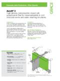
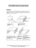
3 PVD s are a very economical replacement for sand Drains . They are relatively inexpensive, provide higher conductivity (up to 30 times more effective than a 300mm diameter sand drain) and can easy be installed at close spacing, thus shortening the path of the pore water in the impermeable soil and expediting the consolidation process. Fig. 1 Effect of Prefabricated Vertical Drains During Consolidation 3 Prefabricated Vertical Drains Applications and Design Guide _____ THE CeTeau Vertical DRAIN SYSTEM CeTeau Vertical Drain is a Prefabricated drainage strip. The core is a highly flexible polypropylene extrusion, having maximum water flow capacity along the grooves formed longitudinally on both sides of the core. Strict quality control is employed to insure the extrusion is consistent. The filter fabric on the CeTeau Vertical Drain is made from strong, durable, non-woven polypropylene or polyester geotextile, having a very high permeability.
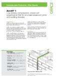
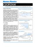
4 The geotextile fabric serves as a filter to allow passage of groundwater into the drain core while preventing piping of fines from the adjacent soils. The filter also serves as and outer skin to maintain the cross-sectional shape and hydraulic capacity of the core channels. The graphic below shows a typical cross-section of the CeTeau Vertical Drain Fig. 2 Cross-section of CeTeau Prefabricated Vertical drain 4 Prefabricated Vertical Drains Applications and Design Guide _____ THE CeTeau Vertical DRAIN SYSTEM CeTeau Vertical Drain is installed using patented, proprietary equipment. The equipment is comprised of a structural mast (which in some cases also serves as equipment housing), a mandrel and mandrel propulsion equipment. The CeTeau Vertical Drain, which is supplied in rolls 250-300m in length, is threaded through the mast into the mandrel and is held in place at the base of the mandrel by an anchor plate.
5 The mandrel and the wick are then driven into the ground to the desired depth. The anchor plate serves two purposes in the operation. First, it prevents soil from entering and clogging the mandrel as it is being driven into the ground, and secondly, it anchors the drain in place at the desired depth as the mandrel is being retracted. When the mandrel has been withdrawn, the wick is cut off above the ground surface, leaving a tail approximately 300mm long. Then a new anchor plate is installed, the mast is repositioned over the next location and the cycle is repeated. There are various means of driving the mandrel, including a simple cable pull powered by a conventional crane, a vibratory head attached directly to the mandrel (although this technique is not recommended because of its detrimental effects on the surrounding soil), and a hydraulic cylinder powered by the hydraulics of an excavator.
6 The hydraulic system has a mechanical advantage, allowing deeper penetration and greater applied force. When stiffer soils are encountered extra weight can be added to the mast to assist penetration or holes can be predrilled before the mandrel and drain are inserted. As the ground surface in areas requiring Prefabricated Vertical Drains is often soft and unstable. It may be necessary to prepare a working mat to facilitate mobility of the installation equipment. This mat also serves a second purpose of providing a free draining layer for the water being discharged from the Drains . This working mat is generally constructed of sand, as part of the preload or structure fill, and is typically 300mm or more in thickness. In the event that good quality natural materials for the working mat are scarce, several options exist to both improve the stability of the surface soil and reduce the thickness of the working mat.
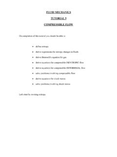
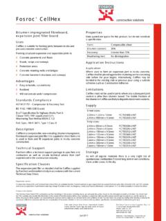
7 Geotextiles or geogrids are very effective in strengthening the sub-base, and can significantly reduce the amount of fill needed to provide a suitable and stable working mat. Efficiency may also be increased by replacing the free draining sand mat with Prefabricated horizontal Drains connected to the protruding wick tails. This is a very effective method to ensure fast and complete removal of all water discharged from the wick drain project. Fig. 3 Consolidation using Prefabricated Vertical Drains 5 Prefabricated Vertical Drains Applications and Design Guide _____ Fig. 4 Consolidation without Prefabricated Vertical Drains THE VACUUM PRELOAD OPTION A preload is usually required to properly compress the saturated soils and cause the water to flow through the Drains to be discharged. When the applied preload becomes part of the structure, as in an embankment or bridge approach, the materials used for the preload are usually selected accordingly.
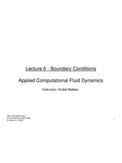
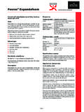
8 However, when the ultimate required elevation is already close to the anticipated elevation after settlement, the added costs of applying the preload, and removing it again after consolidation has occurred, often renders the project economically unviable. An attractive option to reduce costs in the case is to utilize a preload vacuum simulation technique called CeTeau Vacuo . The system consists of installing Prefabricated Vertical Drains , individually connected below the surface to vacuum transmission pipes. These pipes are then connected at surface level to a horizontal tubing system by means of specially developed airtight T-couplings. The so-called drainage screens, a row of Vertical Drains that are connected at the top to a horizontal line, are brought outside the surcharge (if any) and connected to a combined vacuum air pump that has been developed in-house. The applied vacuum produces the same pressures as a traditional preload system of up to 3-5m in height.
9 Fig. 5 Consolidation using Prefabricated Vertical Drains with vacuum preload arrangement 6 Prefabricated Vertical Drains Applications and Design Guide _____ DESIGNING WITH THE CeTeau Vertical DRAIN SYSTEM The principle underlying Vertical drainage is simple, but the theoretical description of the operating mechanism is quite complex. Wick drain spacing is usually calculated by means of Barron s formula, as follows: Ch = D2 1 ln D - + d 2 ln 1 8t 1 - d 2 d D 1 - U n (Formula 1) Where: Ch = Consolidation Coefficient for Horizontal Flow (m2/s) D = Diameter of the Sphere of Influence of the Drain (m) t = Consolidation Time (s) d = Equivalent Diameter of the Drain (m) U = Average Degree of Consolidation The Ch value is determined from laboratory tests of soil samples.
10 The compression test is the most common method, and the Ch value is a function the Cv value thus found. (For clay soils, Ch 1 to 4 times Cv.) Drains are most efficiently placed in a triangular pattern, but they can be arranged in a square pattern (although a triangular pattern is nearly times more efficient). The diameter of the sphere of influence (D in formula 1) is based on the existence of a soil cylinder, and to account for overlap and gaps between such cylinders. The design drain spacing for triangular pattern should be , and that of a square pattern should be times that calculated value of D. The drain diameter (d in formula 1) assumes a cylindrical drain. The equivalent diameter of the CeTeau Vertical Drain is derived from the following equation: d = circumference 7 Prefabricated Vertical Drains Applications and Design Guide _____ At a width of 100mm and a thickness of 3mm, the circumference (perimeter in this case) of the drain is 206mm, making the equivalent diameter of the drain 65mm.