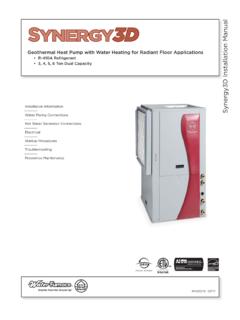
Transcription of Premier Installation Manual - waterfurnace.com
1 WFIIM1555 11/06 Installation InformationWater Piping ConnectionsDesuperheater ConnectionsElectricalStartup ProceduresTroubleshootingPreventive MaintenancePremier Installation ManualGeothermal/Water Source Heat Pumps 3/4 thru 6 Ton2 Premier Installation MANUALM odel NomenclatureFamilyP = PremierUnit CapacityMBTUHD ischarge Air ConfigurationT = Top Discharge VerticalE = End Discharge HorizontalS = Side Discharge HorizontalReturn Air ConfigurationL = LeftR= RightVoltage0 = 208-230/60/1 (Commercial)1 = 208-230/60/1 (Residential)2 = 265-277/60/13 = 208-230/60/34 = 460/60/3 Hot Water Option0 = None1 = Hot Water GenerationWith Factory Installed Pump (Residential)2 = Hot Water GenerationWithout Pump (Commercial 022-066, 230 VAC only)Note:*FX10 available only on units with PSC blowers without Options0 = PSC Blower1 = ECM Blower2 = Oversized ECM Blower Option(040-046 Only)Coax OptionsC = CopperN = CupronickelSound KitA = NoneB = BlanketFilter OptionsD = 1" Pleated DisposableNon-Standard OptionsS = Standard4 = FX10*5 = FX10 w/Open N2 Com.
2 Card*6 = FX10 w/LonWorks Com. Card*7 = FX10 w/BacNet Com. Card*Non-Standard Option DetailsVintageA = All OthersB = P028(Single Phase),P056(All Voltages)P040T L320 CADSS A3 Premier Installation MANUALT able of ContentsGeneral Installation Information 4-7 Closed Loop Ground Source Systems 8 Open Loop Ground Water Systems 9 Boiler/Cooling Tower Closed Loop Systems 10 System Cleaning & Flushing 11 Desuperheater Connection & Startup 12-13 Electrical Connections 15 Electronic Thermostat Installation 15 Wiring Schematics 16-27 Fan Performance Data 28-29 Standard Microprocessor Control Operation 30-31 DIP Switch Settings
3 32-33FX10 Control Operation 34 Startup Procedures 35 Description of Unit Operation 36-37 Troubleshooting 38 Preventive Maintenance 39 Replacement Procedures 404 Premier Installation MANUALS afety Considerations Installing and servicing heating and air conditioning equipment can be hazardous due to system pressure and electri-cal components. Only trained and qualifi ed service personnel should install, repair or service heating and air conditioning equipment. Untrained personnel can perform the basic maintenance functions of cleaning coils and cleaning and replacing fi lters.
4 All other operations should be performed by trained service personnel. When working on heating and air conditioning equipment, observe precautions in the literature, tags and labels attached to the unit and other safety precautions that may apply. Follow all safety codes. Wear safety glasses and work gloves. Use a quenching cloth for brazing operations and have a fi re extinguisher and StorageMove units in the normal up orientation as indicated by the arrows on each carton. Horizontal units may be moved and stored per the information on the carton. Do not stack more than three units in total height. Vertical units may be stored one upon another to a maximum height of two units. Do not attempt to move units while the equipment is received, all items should be carefully checked against the bill of lading to be sure all crates and cartons have been received.
5 Examine units for shipping damage, removing the units from the cartons if necessary. Units in question should also be internally inspected. If any damage is noted, the carrier should make the proper notation on the delivery receipt, acknowledging the damage. Units are to be stored in clean, dry location to prevent Location Locate the unit in an indoor area that allows for easy removal of the fi lter and access panels. Location should have enough space for service personnel to perform maintenance or repair. Provide suffi cient room to make water, electrical and duct connection(s). If the unit is located in a confi ned space, such as a closet, provisions must be made for return air to freely enter the space by means of a louvered door, etc. Any access panel screws that would be diffi cult to remove after the unit is installed should be removed prior to setting the unit.
6 On horizontal units, allow adequate room below the unit for a condensate drain trap and do not locate the unit above supply piping. Care should be taken when units are located in unconditioned spaces to prevent damage from frozen water lines and excessive heat that could damage electrical Vertical Units Vertical units are available in left or right air return confi gurations. Vertical units should be mounted level on a vibration absorbing pad slightly larger than the base to provide isolation between the unit and the fl oor. It is not necessary to anchor the unit to the fl oor (see right). If access to the left side of the unit will be limited after Installation , remove the two mounting screws on the left side of the control box before setting the unit (leave the two front mounting screws intact).
7 This will allow the control box to be removed with only the two front mounting screws for future : Before performing service or maintenance operations on a system, turn off main power switches to the indoor unit. If applicable, turn off the accessory heater power switch. Electrical shock could cause personal Installation InformationFigure 1: Vertical Unit MountingVibrationAbsorbingMeshorAirPad5 Premier Installation MANUALCAUTION: Do not use rods smaller than 3/8-inch diameter since they may not be strong enough to support the unit. The rods must be securely anchored to the Horizontal Units Horizontal units are available with side or end discharge and may be fi eld converted from one to the other by replac-ing the discharge panel with a new panel which must be ordered separately.
8 Horizontal units are normally suspended from a ceiling by four or six 3/8-inch diameter threaded rods. The rods are usually attached to the unit by hanger bracket kits furnished with each unit. Lay out the threaded rods per the dimensions in Figure 3. Assemble the hangers to the unit as shown. Securely tighten the brackets to the unit using the weld nuts located on the underside of the bottom panel. When attaching the hanger rods to the bracket, a double nut is required since vibration could loosen a single nut. To allow fi lter access, one bracket on the fi lter side should be installed 180 from the position shown in the fi gure below. The unit should be pitched approximately 1/4-inch towards the drain in both direc-tions to facilitate the removal of condensate. Use only the bolts provided in the kit.
9 The use of longer bolts could damage inter-nal parts. Some residential applications require the Installation of hori-zontal units on an attic fl oor. In this case, the unit should be set in a full size secondary drain pan on top of a vibration absorbing mesh. The secondary drain pan prevents possible condensate overfl ow or water leakage dam-age to the ceiling. The secondary drain pan is usually placed on a plywood base isolated from the Figure 2: Typical Horizontal Unit Installation DisconnectsBuilding WaterLoopFlexible DuctCollar3/8 Threaded rods (6)HangingBrackets(included)P/T PlugsLine VoltageTo ThermostatInsulatesupply plenumand use at leasta 90 elbow toreduce noiseBall ValvesHose KitsTo LinePowerElectric heatassembly(optional)MODELABCDEP010, P022, 028, P040, 3: Hanger Location and AssemblyCBDEC ompressorSectionAir HandlerSectionAVibration IsolatorWasherHex Nuts(not supplied)Bolt andLockwasher3/8 Threaded Rod(not supplied)P010-034, 4 hangers includedP040-066, 6 hangers included6 Premier Installation MANUALDuct System An air outlet collar is provided on vertical top fl ow units and all horizontal units to facilitate a duct connection.
10 A fl exible connector is recommended for discharge and return air duct connections on metal duct systems. Uninsulated duct should be insulated with a minimum of 1-inch duct insulation. Application of the unit to uninsulated ductwork in an unconditioned space is not recommended as the unit s performance will be adversely affected. If the unit is connected to existing ductwork, check the duct system to ensure that it has the capacity to accommodate the air required for the unit application. If the duct is too small, as in the replacement of heating only systems, larger duct-work should be installed. All existing ductwork should be checked for leaks and repaired if necessary. The duct system should be sized to handle the design airfl ow quietly and effi ciently. To maximize sound attenuation of the unit blower, the supply and return plenums should include an internal duct liner of fi berglass or constructed of ductboard for the fi rst 10 feet.
