Transcription of Premium wheel-end brake products Bendix EB …
1 BBeennddiixx EEBB &&EESS AAiirr DDrruumm BBrraakkeessPremium wheel -end brake productsSSeerrvviiccee MMaannuuaall1 Section 1: General InformationForeword .. 4 Lining Material Warning .. 5 Model Coverage .. 6 Parts Nomenclature .. 8 Model ES-165-7 and EB-165-7 Interchangeability .. 12EB Roller and ES Cam Interchangeability .. 12 Section 2: Periodic ServiceBrake Maintenance Preliminary Steps .. 15 brake Adjustment .. 15 brake Operation Check .. 17 Lubrication .. 17 Periodic Inspections .. 18 Service Intervals .. 18 Section 3: Removal/DisassemblyDrum Removal .. 19 Shoe Removal .. 20EB models (except EB-150-4L)/ES-165-5, 6, 7D, F, L/ES-150-8D, F/ES-150-6D .. 21ES-150-4L and EB-150-4L .. 23ES-165-7M .. 24ES-165-7H .. 26 brake Adjuster Removal .. 28 Camshaft Removal .. 28 Air Chamber Bracket Removal .. 28 Spider Removal .. 29 Dustshield Removal .. 29 Cleaning brake Parts .. 30 Section 4: InspectionDrum Inspection.
2 31 Shoe and Lining Inspection .. 32 Camshaft Radial Play Inspection .. 34 Camshaft Inspection .. 34 Camshaft Bushing and Seal Inspection .. 34 Spider Inspection .. 35 Air Chamber Bracket Inspection .. 35 Air Chamber Inspection .. 36 brake Adjuster Inspection .. 36 Section 5: Repair/ReplacementCamshaft Bushing/Grease Seal Replacement .. 37 Lining Replacement .. 38 Section 6: Installation/AssemblySpider Installation .. 39 Dustshield Installation (Two Piece) .. 39 Dustshield Installation (One Piece) .. 40 Air Chamber Bracket Installation .. 41 Camshaft Installation .. 42 Cam Head Washer Installation .. 42 brake Adjuster Installation .. 43 Shoe and Lining Installation .. 44 Shoe Installation .. 46ES-150-8D, F & 6D .. 46 All EB (except EB-150-4L) and ES-165-5, 6, 7D, F, L .. 47ES-165-7M .. 49ES-165-7H .. 51 Specification 57 General Information2 List of IllustrationsFigure 1. How to Use this Manual.
3 4 Figure 2. Bendix brake Model Identification .. 5 Figure 3. brake Part Nomenclature, General .. 6 Figure 4. brake Model Part Nomenclature .. 7 Figure 4. brake Model Part Nomenclature, Continued .. 8 Figure 5. EB Roller and ES Cam Contact Pattern .. 12 Figure 6. Parts Identification .. 13 Figure 6. Parts Identification, Continued .. 14 Figure 7. Vehicle Maintenance Support .. 15 Figure 8. Measurement, At Rest .. 15 Figure 9. Measurement, 80 psi Applied .. 16 Figure 10. Measurement, brake Applied .. 16 Figure 11. brake Adjuster Adjustment .. 16 Figure 12. Roller Retainer Removal .. 21 Figure 13. Upper Cam Roller and Pin Removal .. 21 Figure 14. ES-165-7D, L, F Shoe Removal .. 22 Figure 15. Shoe Removal .. 22 Figure 16. Shoe Return Spring Removal .. 23 Figure 17. Lower Shoe Removal .. 23 Figure 18. Retainer Loop Removal .. 24 Figure 19. Roller and Retainer Removal .. 24 Figure 20.
4 Return Spring Removal .. 24 Figure 21. Retaining Ring and Washer Removal .. 25 Figure 22. Cap Screw Removal .. 25 Figure 23. Anchor Pin Removal .. 25 Figure 24. Anchor Pin Bushing Removal .. 25 Figure 25. Retaining Ring and Washer Removal .. 26 Figure 26. Cap Screw Removal .. 26 Figure 27. Anchor Pin Removal .. 26 Figure 28. Shoe Removal .. 26 Figure 29. Anchor Pin Bushing Removal .. 27 Figure 30. Groove Pin Removal .. 27 Figure 31. brake Adjuster Removal .. 28 Figure 32. Spider Mounting Hardware Removal .. 29 Figure 33. Dustshield Mounting Hardware Removal .. 29 Figure 34. Drum Inspection .. 31 Figure 35. Cam Roller Identification .. 31 Figure 36. Shoe and Lining Inspection .. 32 Figure 37. brake and Lining Blocks .. 33 Figure 38. Camshaft Radial Play Inspection .. 34 Figure 39. Camshaft Inspection .. 34 Figure 40. Spider Inspection .. 35 Figure 41. Air Chamber Bracket Inspection.
5 35 Figure 42. Air Chamber Inspection .. 36 Figure 43. brake Adjuster Inspection .. 36 Figure 44. Air Chamber Bracket Bushing Installation .. 37 Figure 45. Camshaft Bushing Installation .. 37 Figure 46. Lining Rivet (or Bolt) Tightening Sequence .. 38 Figure 47. Installing Spider Mounting Hardware .. 39 Figure 48. Dustshield Spacing .. 39 Figure 49. Designed Interference Fit .. 39 Figure 50. Attaching Screw Location .. 40 Figure 51. Air Chamber Bracket Mounting Hardware .. 41 Figure 52. Camshaft Installation .. 42 Figure 53. Cam Head Washer Installation .. 42 Figure 54. Shim Washer and Snap Ring Installation .. 43 Figure 55. brake Adjuster End Play Check .. 43 Figure 56. brake Adjuster Lubrication and Adjustment .. 43 Figure 57. Shoe Web Lubrication .. 45 Figure 58. Shoe Retaining Spring Installation .. 45 List of Illustrations and TablesGeneral Information3 List of IllustrationsFigure 59.
6 Shoe Return Spring and Roller Installation .. 45 Figure 60. Upper and Lower Shoe Positioning .. 46 Figure 61. Shoe Return Spring Installation .. 46 Figure 62. Upper and Lower Shoe Positioning .. 47 Figure 63. Shoe Return Spring Installation .. 47 Figure 64. Roller Retainer Installation .. 48 Figure 65. Shoe Return Spring Installation .. 48 Figure 66. Retainer Installation .. 48 Figure 67. Anchor Pin Bushing Installation .. 49 Figure 68. Lower Shoe and Anchor Pin Installation .. 49 Figure 69. Upper Shoe and Anchor Pin Installation .. 49 Figure 70. Cap Screw Installation .. 49 Figure 71. Shoe Return Spring Installation .. 50 Figure 72. Roller Retainer Installation .. 50 Figure 73. Roller and Retainer Installation .. 50 Figure 74. Retainer Installation .. 50 Figure 75. Groove Pin Installation .. 51 Figure 76. Spider Anchor Pin Bushing Installation .. 51 Figure 77. Shoe Anchor Pin Bushing Installation.
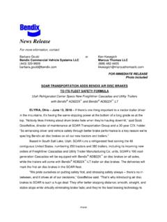
7 51 Figure 78. Lower Shoe Positioning .. 52 Figure 79. Upper Shoe Positioning .. 52 Figure 80. Upper Shoe Installation .. 52 Figure 81. Lower Shoe and Anchor Pin Installation .. 52 List of TablesTable 1. Bendix brake Models and Specifications .. 4 Table 2. Distance Range .. 15 Table 3. Stroke Values .. 16 Table 4. Lubrication Intervals .. 17 Table 5. Shoe Removal Procedure Index .. 20 Table 6. Distance: Clevis Pin Hole Centerline to Air Chamber Face .. 36 Table 7. Camshaft Bushing Installation Specifications .. 37 Table 8. Shoe Installation Procedure Index .. 44 List of Illustrations and TablesGeneral Information4 Foreword/Lining Material WarningHow to Use this Manual1. Arrangement. This manual is arranged in seven sections:General Information, Periodic Service, Removal/Disassembly,Inspection, Repair/Replacement, Installation/Assembly andSpecifications. General page layout, including section andparagraph headings, indention levels, and Figure and Tabledesignator information, is shown in Figure Table of Contents.
8 The Table of Contents lists all sectionheadings and primary paragraph headings in Illustrations and Tables. Illustrations and tables are includedto help make the text of this publication clear. See the List ofIllustrations and List of Tables following the Table Specification Chart. A tabulation of all measurementspecifications is provided at the back of this of this ManualThis Bendix Spicer Foundation brake LLC publication isintended to act as a source of maintenance informationto those involved in servicing Bendix Information5 DANGERAVOID CREATING DUSTPOSSIBLE CANCER AND LUNG DISEASE HAZARDW hile Bendix Spicer Foundation brake LLC does not offer asbestosbrake linings, the long-term effects of some non-asbestos fibershave not been determined. Current OSHA Regulations coverexposure levels to some components of non-asbestos linings but notall. The following precautions must be used when handling AVOID CREATING DUST.
9 Compressed air or dry brushing mustnever be used for cleaning brake assemblies or the work Bendix SPICER FOUNDATION brake LLC RECOMMENDS THATWORKERS DOING brake WORK MUST TAKE STEPS TO MINIMIZEEXPOSURE TO AIRBORNE brake LINING PARTICLES. Properprocedures to reduce exposure include working in a well ventilatedarea, segregation of areas where brake work is done, use of localfiltered ventilation systems or use of enclosed cells with filteredvacuums. Respirators approved by the Mine Safety and HealthAdministration (MSHA) or National Institute for OccupationalSafety and Health (NIOSH) should be worn at all times duringbrake Workers must wash before eating, drinking or smoking; showerafter working, and should not wear work clothes home. Workclothes should be vacuumed and laundered separately Material safety data sheets on this product , as required byOSHA, are available from Bendix Spicer Foundation brake WarningGeneral Information!
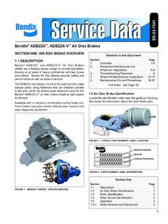
10 6 The service procedures and specifications in this publicationcover the Bendix brake models listed in Table 1. The basicinstructions cover all 15", ", and 18" brake types and sizes,unless specified otherwise. A breakdown of Bendix brake modelidentification is provided in Figure x 4381 x 102 FabricatedFabricatedSAPS teer x 5419 x 127 FabricatedCastSAPS teer or Drive x 5419 x 127 FabricatedFabricatedSAPS teer or Drive x 6419 x 152 FabricatedCastSAPS teer or Drive x 6419 x 152 FabricatedFabricatedSAPS teer or Drive x 7419 x 178 FabricatedCastSAPS teer or Drive x 7419 x 178 FabricatedForgedSAPT railer x 7419 x 178 FabricatedFabricatedSAPS teer or Drive x x 219 FabricatedCastSAPD rive x x 219 FabricatedFabricatedSAPD rive x 7457 x 178 CastHeavy CastSAPOn/Off Hwy. Drive x 4381 x 102 FabricatedFabricatedSAPS teer x 4381 x 102 FabricatedCastSAPS teer x 6381 x 152 FabricatedCastSAPS teer or Drive x x 219 FabricatedCastSAPD rive x x 219 FabricatedForgedSAPT railer x 5419 x 127 FabricatedCastSAPS teer or Drive x 5419 x 127 FabricatedFabricatedSAPS teer or Drive x 6419 x 152 FabricatedCastSAPS teer or Drive x 6419 x 152 FabricatedFabricatedSAPS teer or Drive Axles165 XL x 6419 x 152 CastCastDAPS teer Axle x 7419 x 178 FabricatedCastSAPS teer or Drive x 7419 x 178 FabricatedForgedSAPT railer x 7419 x 178 CastHeavy CastDAPOn/Off Hwy.