Transcription of PRESS-FIT TECHNOLOGY
1 TE AUTOMOTIVE /// W H I T E PA P E RPRESS-FIT TECHNOLOGYA uthors: Joakim Mattsson, Thorsten Callies, Bart KerckhofTE AUTOMOTIVE /// W H I T E PA P E RINTENTION OF THIS WHITEPAPER IS TO GIVE A BRIEF SUMMARY OF THE PRESS-FIT TECHNOLOGY AT TE CONNECTIVITY SINCE THIS IS A MAJOR TERMINATION TECHNIQUE THAT IS STILL GAINING IMPORTANCE AS IT IS APPLIED IN MORE AND MORE PRODUCTS. THE PRESS-FIT TECHNOLOGY IS A solder -LESS TERMINATION TECHNOLOGY USED IN ELECTRICAL SYSTEMS THROUGHOUT THE INTERCONNECTION INDUSTRY, WHICH MECHANICALLY AND ELECTRICALLY JOINS A PRESS-FIT CONTACT TO A PRINTED CIRCUIT BOARD (PCB).Table of Contents 1 Introduction 2 2 Overview PRESS-FIT solutions 3 3 Market trends 4 4 Materials 5 5 Comparison PRESS-FIT vs soldering 6 6 Benefits with PRESS-FIT 7 7 Product characteristics and qualification 8 8 Application overview 9 9 Application tooling 11 10 Future / New development 13 11 Legal Details 14 PRESS-FIT TECHNOLOGYPRESS-FIT TECHNOLOGYTE AUTOMOTIVE /// W H I T E PA P E R31 | IntroductionThis document is an introduction to the PRESS-FIT principle for a PRESS-FIT connection is that a contact terminal is pressed into a printed circuit board (PCB).
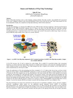
2 There are two types of PRESS-FIT pins; the solid pin having a solid press-in zone and the compliant pin having an elastic press-in zone. In this whitepaper only the PRESS-FIT pin having an elastic press-in zone is described and it is called the PRESS-FIT TECHNOLOGY from TE Connectivity (TE) was first introduced in the telecommunication industry in the 1970s. Later, in 1988, the first PRESS-FIT pin from TE Connectivity was introduced in the automotive industry. Today TE Connectivity offers two distinctive PRESS-FIT solutions for automotive applications: ACTION PIN and Multispring pin (see Picture 1) which are both compliant pin designs featuring an elastic behavior during the pin the following chapters several different PRESS-FIT aspects will be described and discussed in terms of functionality, properties, characteristics and applications focused on the auto-motive s PRESS-FIT solutions in fact are compliant pins fea-turing an elastic behavior and thus will deform during insertion (significantly reducing stress on the PCB holes compared to solid PRESS-FIT pin which do no more exist in automotive applications) and sustain a permanent contact normal force when inserted to enable a reliable electrical and mechanical connec-tion over , high contact normal forces between compliant pin and plated through hole (commonly)
3 Generate cold welded interconnections autono-mously after the pin insertion; especially, if tin plat-ing is used for at least one of both contact partners (pin/hole). Due to these cold welding processes intermetallic connections are generated leading to excellently low contact resistance values (commonly below / in sub-Milliohm range). Further-more, the mechanical stability is significantly pin and plated through hole (PTH) summa-rize together to a PRESS-FIT system. The functionality of such a system is dependent of the properties / characteristics of both of the components and their interactions (see also chapter 7).Picture 1 The pictures show an ACTION PIN PRESS-FIT pin (above) and a Multispring PRESS-FIT pin (below). PRESS-FIT TECHNOLOGYTE AUTOMOTIVE /// W H I T E PA P E R42 | Overview PRESS-FIT solutionsThe PRESS-FIT TECHNOLOGY is widely applied in multiple automotive applications.
4 Various customers are using PRESS-FIT TECHNOLOGY in a great variety of convenient, assistance and safety applications demonstrating the high acceptance of TE s PRESS-FIT products and the PRESS-FIT termination TECHNOLOGY , TE s product portfolio could be distin-guished into two major solution groups: PRESS-FIT contact terminals (for single pin insertion) and con-nector modules (for mass termination). The PRESS-FIT terminals for single pin insertion com-monly are supplied in a reeled condition allowing the customers to apply the contacts on their PCB s in a free and highly flexible manner. Connector modules commonly feature highly cus-tomized housing components equipped with con-tacts (and other sub-components) in a potentially modular way according to the specific customer 2:Single pin insertion ACTION PIN inserted into a PCB (above) and mass termi-nation with a four row (>100 PRESS-FIT pins) 90 header module (below).
5 PRESS-FIT TECHNOLOGYTE AUTOMOTIVE /// W H I T E PA P E R53 | Market TrendsThe electronics in vehicles is between 2011 and 2016 expected to grow year over year. With that growing electronics intelligent bus systems replace simple cable connections and intelligent distribution boxes replace simple information systems, computerized motor control management will enhance safety, perfor-mance and comfort. With more electronics also the amount of electrical connections in vehicles are con-tinuously increasing. In parallel there is a trend that vehicles are becoming smaller, safer, cheaper and better. New applications are mostly controlled by an electrical con-trol unit (ECU) that needs to be as com-pact as possible. Inside each ECU there is a PCB carrying the electrical components that follows the same trend of a consequence of the electronification and miniaturization, more electrical interconnections are required on the same or even smaller packaging space.
6 This drives the development to miniaturized interconnection meet this trend TE Connectivity has recently launched the miniaturized contact system NanoMQS product family for pins (see picture 3). In order to use less PCB space the pitch (distance between two contacts) for the NanoMQS contact system has been reduced from to in combination with a PTH size reduction from the standard to the type. Depending on the configuration it has been seen that this gives the opportunity to save up to 60% space compared to the standard MQS interconnection system using pins. There is also a trend to use the NanoMQS contacts together with PRESS-FIT TECHNOLOGY and therefore TE Connectivity currently develops a new PRESS-FIT pin, the demanding tougher environmental conditions and increased functional performance pushes the electrical interconnections including PRESS-FIT contacts to be more reliable.
7 Also, with more electrical interconnections the requirements on each single component increase as the functionality over lifetime must be ensured for improved quality and today the most common PCB thickness in automotive applications is in future applications we may see thinner PCB s towards , or thicknesses. The PRESS-FIT solution needs as well to cope with this trend in addition to more demanding PRESS-FIT TECHNOLOGY can offer many advantages that fit very well to the trends in the market and it can potentially be used in every contact-to-PCB 3 Showing space saving with NanoMQS vs MQS pin header TECHNOLOGYTE AUTOMOTIVE /// W H I T E PA P E R64 | MaterialsThe PRESS-FIT pin can be made of different base materials featuring two galvanic layers, the under-plating and the top plating, in a sandwich structure. The picture 4 shows the most common materials and layers used in the automotive 4 The picture shows the typical materials used for PRESS-FIT TECHNOLOGYTE AUTOMOTIVE /// W H I T E PA P E R75 | Comparison PRESS-FIT vs solderingWith the conversion to lead free soldering an increase of the average soldering tempera-ture are required.
8 To cope with this higher temperature, special and more expensive plastic materials like LCP, PPS, PPA and PCT are needed. This disadvantage can be avoided by using PRESS-FIT TECHNOLOGY and discard the soldering process. In that way no expensive high temperature plastics are needed for a lead-free application. As space is an important factor in automotive applications the PRESS-FIT TECHNOLOGY provides a solution which would be very difficult to realize with a conventional soldering process for the PRESS-FIT TECHNOLOGY offers a solution for big connectors in combination with a reflow soldering process. In manufacturing electronic devices surface mounting TECHNOLOGY (SMT) is a state of the art soldering process step applying numerous electronic compo-nents to a PCB. Large soldering headers often disturb the SMT reflow process.
9 The pins of the header and neighboring components are obtaining a too low temperature, resulting in a defective soldering process. This can be solved by adding the header after the soldering process by means of PRESS-FIT PRESS-FIT pin insertion process is fast, cheap and reliable manufacturing process that allows a repair of the PRESS-FIT pin up to two important aspect of PRESS-FIT TECHNOLOGY is reliability. The PRESS-FIT connection is considered as one of the most reliable connection techniques. The reliability shown in the IEC1709 norm, shows that the PRESS-FIT connection has a fit-rate of (see table 1), which is at least 10 times more reliable than soldering or IDC connections. Table 1 Reliability table shows comparison between different electrical connection TECHNOLOGYTE AUTOMOTIVE /// W H I T E PA P E R86 | Benefits with press-fitPress-fit TECHNOLOGY is a solder -less termination enabling a permanent electrical and mechan-ical terminal-to-PCB connection with several distinctive advantages:n Fast processing > comparative data: lead time soldering vs.
10 Press-fitn Use of standard resins instead of cost intensive heat stabilized resins in the headern Prevents thermal treatment to the headern Flexible application designs with single pin insertion due to freely programmable pin arrays in terms of pin numbers and orientationn Stand-alone pin insertion possiblen Lubrication and flux aid free processingn Prevents solder paste printing and pre-heatingn Environmental friendlyn No shading-off issues with large header components in post-soldering insertionn Prevents soldering defects like bridges, bad wetting, flux residuals, solder balls, spider webs thermal load and cold solder jointsOf course, matching application equipment is needed to manufacture PRESS-FIT TECHNOLOGY related modules (instead of soldering equipment). Since this is commonly highly flexible and automated the machinery equipment can be used for several different products and applications.