Transcription of PRESSURE AND FUNCTIONAL TESTING API 598 - Global …
1 Global Supply Line Pty Ltd ABN 86 008 134 512 Head Office - 1 to 19 Barndioota Rd Salisbury Plain South Australia 5109 Ph +61 (0)8 8285 0000 Fax +61 (0)8 8285 0088 AND PIPELINE SUPPLIESADELAIDE BRISBANE PERTHPRESSURE AND FUNCTIONAL TESTING API 598 Technical Instruction AP/PT5 Review:00 Date:05/03/19 Page:1/3 Issued by:GPApproved by:BTLIST OF valves AS PER API 5981. SHELL HYDROSTATIC TEST Scope: 100% of batch. TESTING PRESSURE : See table N 1 TESTING times: See table N 2 Acceptance criteria: See table N 31. Mount the valve on the test-bed, closing off the inlet and outlet ports, and with the disc/ball in the half open position, fill the interior completely with water until it overflows through the vent connection provided in the upper test flange. The stem must be accessible to operate the Close the vent Valve shall be operated for one complete open/close cycle, then half open (at least 10 to ensure pressurisation of the cavity).
2 4. Check for the absence of leaks at the temporary joints, used for the test. Dry the external surface of the Apply the required test PRESSURE as per Table No. 1 & Table No. 2 pressures & durations shown below. Close the water inlet and maintain the PRESSURE for the required Leaks through the PRESSURE retaining parts are not permitted, except through the temporary joints, which are installed for the carrying out of the test, and only provided that they do not obstruct the interpretation of the results. Permanent deformations will not be HYDROSTATIC TESTING OF SEATSThis test is optional depending on size, class and type but is carried out for standard. Scope: 100% of batch. To apply from both directions (except check valves ). TESTING PRESSURE : See table N 1 TESTING times: See table N 2 Acceptance criteria: See table N 31.
3 Close off the valve inlet and outlet ports with The valve is adjusted until the ball/disc is in a half open The valve is filled with water through the lower flange, until it overflows from the venting in the upper The valve is operated until it closes and is pressurised through the lower The PRESSURE is maintained for the required time as per Table No. 1 & Table No. 2 pressures & durations shown below, and it is checked that there are no drops from the drain / vent and upper flange vent. (The leakage shall be measured in opposite side only when there is no provision of drain/vent)6. As per Table No. 3 The valve is operated to open under PRESSURE , checking that the actuating device is Follow the same operation for the other See pressures and TESTING times as per Table No. 1 & Table No. SUPPLY LINEPRESSURE AND FUNCTIONAL TESTING API 598 Technical Instruction AP/PT5 Review:00 Date:05/03/19 Page:2/3 Issued by:GPApproved by:BT3.
4 PNEUMATIC TESTING OF TIGHTNESS SEATSNot performed on metal seated check valves . Scope: 100% of batch. To apply from both directions. TESTING PRESSURE : Between 4 & 7 bars TESTING times: See table N 2 Acceptance criteria: See table N 3 This test is optional depending on size, class & type but on API 608 valves and API 600 gate valves it is always performed by The valve inlet and outlet are closed off with The valve is adjusted until the ball/disc is in a half open The valve is filled with dry, clean and oil free nitrogen or air through the lower flange. If the air test PRESSURE is above 10 barg the test must be carried out with the valve submerged in water, for safety The valve is adjusted until it is in the closed The PRESSURE is released through the upper flange and it is connected to a tube with an internal diameter of 4mm, the end of which is submerged between 3 and 6mm below the surface of Acceptance criteria: Refer to Table No.
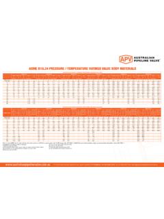
5 3 The valve is operated until it opens, it is pressurised again to the test PRESSURE , then closed again and the PRESSURE is released through the lower flange, checking the lower closure for As per Table No. 1 & Table No. 2 pressures & durations shown belowTABLE No 1 SHELL AND SEAT HYDRO TESTING x PN (bar) x PN (bar)150#3022300#7856600#156114800#20415 2900#2331711500#3882812500#647474 Note: This PRESSURE is applicable for A105N, LF2, WCB, LCC, F304, F316, CF8M, CF8, CF3M, CF3 for other materials see No 2 TESTING MINIMUM TIMES (SECONDS)DNTESTSS hellSeats 50NB (2 )151565NB ~ 150NB (2 1/2 - 6 )6060200NB ~ 300NB (8 - 12 )120120 350NB (14 )300120 NOTE: These are minimum test times, GSL test durations are equal or SUPPLY LINEPRESSURE AND FUNCTIONAL TESTING API 598 Technical Instruction AP/PT5 Review:00 Date:05/03/19 Page:3/3 TABLE No 3 MAXIMUM PERMISSIBLE LEAK FOR SEATS TESTINGDNSOFT SEATMETAL SEAT VALVE* metal SEAT CHECK VALVEW aterAirWater (drops per minute)Air (bubble per minute)Water (cm3/min)Air (litres per minute) 2 00061,332 1/2 05107,51,833 061292,174 0816122,835 01020153,506 01224184,178 01632245,6710 02040307,0012 02448368,3314 02856429,8316 032644811,1718 036725412,6720 040806014,0024 048967216,8326 0521047818,1728 0561128419,6730 0601209021,0032 0641289622,3336 07214410825,1740 08016012028,0042 08416812629,3348 09619214433,671 Millilitre = 16 drops ; 1 Millilitre = 7 bubbles* ISO 5208 or ANSI/FCI 70 leakage rates can also be FUNCTIONAL TESTING - API 598 - AS