Transcription of Pressure Changers
1 47 Pressure Changers In this section, we cover two model libraries: the Pressure Changers . The modules in this library deal with parts of the process that has an effect on changing the Pressure either directly, such as pumps or compressors, or through its operation, such as pipes and pipelines. It is usually required when handling fluid streams to change its Pressure for different reasons. For example, in the gas sweetening plants, an absorption column might be needed to operate at high pressures to improve the absorption and a pump might be used to compress the inlet fluids to the desired value. On the other hand, the regeneration column must be operated at near atmospheric conditions to allow the adsorbed gases to leave the liquid.
2 The liquid which comes from the absorption column at high pressures is passed through a valve to achieve the design Pressure . Other operations require transportation of fluids. During transportation, hydrostatic pressures and friction causes a Pressure drop. Therefore, pumps and compressors are needed to provide the required energy, by increasing the Pressure , to the required level. The friction losses in pipes are a common cause for Pressure drop, especially when with long pipelines. Therefore, pressures drops must be calculated to determine the required pumping through the pipelines, which is a common calculation when dealing with pipe networks (specifically for oil and gas collecting systems).
3 Pumps In general, a pump is a device used to transport liquids, gases, and slurries. However, the term pump is usually used to refer to liquid handling equipment (this is true with Aspen Plus). The purpose of the pump is to provide a certain Pressure at certain flow rate of a process stream. The Pressure requirement is dictated by the process and piping involved, while the flow rate is controlled by the required capacity in the downstream units. There are several types of pumps used for liquid handling. However, these can be divided into two general forms: positive displacement pumps (including reciprocating piston pump and the rotary gear pump), and centrifugal pumps.
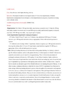
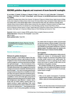
4 The selection of the pump type depends on many factor including the flow rate, the Pressure , the nature of the liquid, power supply, and operating type (continuous or intermittent). Figure 30 shows a general guideline to selecting pump type based on flow rates and discharge Pressure . Centrifugal pumps, such as the one shown in Figure 31, are by far the most widely used type in the chemical process industry, with other types employed for special process specifications ( , high pressures). Dr. YA Hussain 48 Figure 30. Pump selection guide. 2 Figure 31. Section of centrifugal pump showing the inlet (horizontal), the outlet (vertical), the impeller, and the shaft connecting the impeller to the The power requirement for a mechanical system, like pumps and compressors, is given by the general mechanical balance equation: ( ( ) ) (1) 2 R.
5 K. Sinnott, John Metcalfe Coulson, and John Francis Richardson, Coulson & Richardson's Chemical engineering Design, vol. 6, 4th ed. (Butterworth-Heinemann, 2005). 3 J R Backhurst et al., Chemical Engineering Volume 1: Fluid Flow, Heat Transfer and Mass Transfer v. 1, 6th ed. (A Butterworth-Heinemann Title, 1999). 49 All terms in this equation take their normal meaning with m being the mass flow rate, and a coefficient used to take into account the velocity profile inside the pipe (for laminar = , while for turbulent = 1). The required work (or power) given by P is the total work that needs to be delivered to the fluid. This work will be drawn from a motor (operated with electricity or engines).
6 The conversion between the motor and pump power is not complete and an efficiency is defined to describe the power conversion. The efficiency is given by: (2) The input power can be measured from the source. For example, if the pump is operated with electricity, the input power will be I V (current times voltage). The outlet power can be determined using Equation (1). Notices that Equation (1) takes into account all power requirements: from the kinetics, potential, Pressure differences, and any friction losses. The term "Head" is used to express the different parts of the power, or energy, requirements.
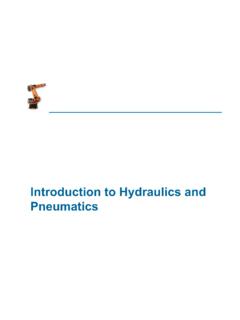
7 The head is a measure of how high the fluid can be reached and is usually expressed in length units (m, ft) which. The pump head is generally divided into three parts: 1. Static head ( z term): the height to which the fluid will be pumped. 2. Pressure head ( term): the Pressure to which the fluid will be delivered (in a pressurized vessel for example). The Pressure units must be converted to length units using relation. 3. System or dynamic head (F term): the energy lost due to friction in pipes, valves, fittings, etc. Figure 32. Typical characteristic curve for a pump. Dr. YA Hussain 50 As the pump works, it can convert its energy into kinetic energy (velocity) or Pressure head.
8 The relation between the flow (kinetic) and the Pressure head is usually expressed using a pump characteristic curve that shows the head developed against the flow rate. The characteristic curve is a function of the pump design (impeller diameter and rpm). A typical characteristic curve is show in Figure 32. The figure also shows the power requirement and pump efficiency of the pump as a function of flow rate. At a certain flow rate, the pump efficiency will be a maximum, and this will be referred to as the best efficiency point ( ). This point represents the ideal combination of flow rate and heat at which the pump can be operated.
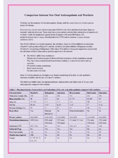
9 In other words, the maximum amount of power input is converted into the fluid. Pump manufacturers usually supply a characteristic diagram with the pump model. A typical diagram is shown in Figure 33. The diagram shows different heat-flow rate curves and the corresponding efficiencies. You can see from this diagram that the efficiency raises as the Pressure (or heat) is increased then it falls again, as indicated earlier. These curves can be used to select the best pump for a given operation. Consider, for example, a process in which you want to pump 40 m3/h of a fluid against a 150 m head. Then, according to Figure 33, impeller (b) will give an efficiency of about 62% with almost the required conditions.
10 If we increase the head to 190 m, impeller (a) can be used with slightly higher efficiency. The choice of the impeller will thus depend on the process conditions. Figure 33. A typical characteristic diagram. Lines (a) through (e) represents decreasing impeller diameter. Notice the curve is given at 2950 rpm operation. 51 Another important definition for pump operation the net positive section head (NPSH). To understand the importance of the NPSH, let us consider first the pump operation. The inlet of the pump is referred to as the suction side while the outlet is referred to as the discharge side. At the suction side, we should ensure that we have enough Pressure to prevent vaporization of the liquid by ensuring the Pressure is higher than the vapor Pressure .