Transcription of Pressure relief valve, pilot operated - Kanflu
1 1/20 Information on available spare parts: relief valve, pilot operated Types DB and DBWS izes 10 to 32 Component series 5 XMaximum operating Pressure 350 barMaximum flow 650 L/minRE 25802 : of contentsFeatures For subplate mounting: Porting pattern to ISO 6264-AR-06-2-A (size 10), ISO 6264-AS-08-2-A (size 25), ISO 6264-AT-10-2 A (size 32) For threaded connection For installation into manifolds 4 adjustment elements for Pressure setting, optional: Rotary knob Sleeve with hexagon and protective cap Lockable rotary knob with scale Rotary knob with scale 5 Pressure stages solenoid operated unloading via built-on directional spool valve or directional poppet valve Heavy duty solenoid Explosion-protected solenoid (on enquiry) Switching shock damping, optional (only type DBW) Further information.
2 High-performance directional valves RE 23178 and RE 22058 Subplates RE 45064H6988 + H6089 Contents PageFeatures 1 Ordering code 2 Cable sockets 3 Symbols 4 Standard types 4 General notes 5 Function, section 5, 6 Technical data 7 Characteristic curves 8, 9 Unit dimensions 10 to 14 Type-tested safety valves of type DB(W)..E, component series 5X, to Pressure Equipment Directive 97/23/EC (in the following PE in short) Ordering code 15 Deviating technical data 16 Safety notes 16 to 182/20 Bosch Rexroth AG HydraulicsDB, DBW RE 25802 codeWithout directional valve = No codeWith built-on directional valve = W pilot operated valve (complete) = No codePilot valve without main spool insert (do not enter size) = CPilot valve with main spool insert = C (enter valve size 10 or 30)
3 pilot valve without main spool insert for subplate mounting = T 1) (do not enter size)SizeOrdering codeSubplate mounting No code Threaded connection G 10= 10 = 10 (G1/2)16 = 15 (G3/4)25= 20 = 20 (G1)25 = 25 (G1 1/4) 32= 30 = 30 (G1 1/2)ABP TabNormally closed= A 2)ABP TabNormally open= B 2)For subplate mounting and installation into manifolds = No codeFor threaded connection = GAdjustment element for Pressure adjustmentRotary knob = 1 Sleeve with hexagon and protective cap = 2 Lockable rotary knob with scale = 3 3)Rotary knob with scale = 7 With main spool 24 mm (all sizes) = With main spool 28 mm (only for size 32) = NComponent series 50 to 59 (50 to 59.
4 Unchanged installation and connection dimensions) = 5 XPressure setting up to 50 bar = 50 Pressure setting up to 100 bar = 100 Pressure setting up to 200 bar = 200 Pressure setting up to 315 bar = 315 Pressure setting up to 350 bar = 350DB5X1) DBT/DBWT corresponds to DBC/DBWC, but with plugged central bore 2) Ordering code required only for version with built-on direc-tional valve (DBW).3) H-key with material no. R900008158 is included in the scope of ) Data sheet RE 23178 (directional spool valve) or RE 22058 (directional poppet valve)5) Cable sockets, separate order, see page ) Ordering code required only for version with built-on directional valve and switching shock damping feature ( ).
5 7) Possible only up to Pressure stage 315 bar8) Hyphen required only for version with built-on directional valve (DBW), without indication of U or S .9) Not for version DBC/DBWCFor ordering code for type-tested safety valves , see page Bosch Rexroth AGRE 25802 DB, DBW3/20 Further details in clear text Type testingNo code = Without type testingE = Type-tested safety valve according to PED 97/23/ECSeal materialNo code = NBR seals V = FKM seals (other seals on enquiry) Caution! Observe compatibility of seals with hydraulic fluid used!
6 R12 6) = Orifice mm in channel B of the directional valveElectrical connectionK4 2; 5) = Without cable socket Individual connection with component plug to DIN EN 175301-803N9 2) = With concealed manual override (standard)N 2) = With manual override No code = Without manual override G24 2) = 24 V DCW230 2) = AC voltage 230 V 50/60 HzNo code = Without directional valve6E 2) = With directional spool valve (high-performance valve 4)) up to 350 bar set pressure6SM 2) = with directional poppet valve (high-performance valve 4))
7 Up to 350 bar set pressureNo code = Without switching shock damping featureS = With switching shock damping feature (only with version DBW)No code = Standard versionU 7) = Valve for minimum cracking Pressure (not for version without main spool insert and not suitable for cross- relief function!) pilot oil supply and pilot oil drain (see also symbols on page 4) 8) = pilot oil supply and pilot oil drain internalX = pilot oil supply external, pilot oil drain internal 9)Y = pilot oil supply internal, pilot oil drain externalXY = pilot oil supply and pilot oil drain external 9)*Cable sockets to DIN EN 175301-803 For details and further cable sockets, see RE 08006 ColourMaterial circuitryWith indicator lamp 12.
8 240 VWith rectifier 12 .. 240 VWith indicator lamp and Zener-diode suppressor circuit 24 VGreyR901017010 BlackR901017011R901017022R901017025R9010 17026 Further standard types and components can be found in the EPS (standard price list).4/20 Bosch Rexroth AG HydraulicsDB, DBW RE 25802 typesTypeMaterial numberDB 10-2-5X/50R900590645DB 10-2-5X/100R900590646DB 10-2-5X/200R900587772DB 10-2-5X/315R900590334DB 10-2-5X/350R900597992DB 20 -2-5X/50R900597212DB 20 -2-5X/100R900589433DB 20 -2-5X/200R900590768DB 20 -2-5X/315R900593530DB 20 -2-5X/350R900590618DB 20 G2-5X/50R900590328DB 20 G2-5X/200R900597307DB 20 G2-5X/315R900597747DB 20 G2-5X/350R900599232 TypeMaterial numberDB 30-2-5X/50R900593564DB 30-2-5X/100R900594677DB 30-2-5X/200R900588131DB 30-2-5X/315R900591128DB
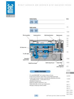
9 30-2-5X/350R900504902DB 30 G2-5X/50R900598338DB 30 G2-5X/100R900502598DB 30 G2-5X/200R900500719DB 30 G2-5X/315R900594426DB 30 G2-5X/350R900535222 SymbolsType ..Type ..Type closedTPABP TabABP TabNormally closedTPABP TabXABP TabNormally openNormally openType closedTPABP TabYABP TabNormally closedTPABP TabX YABP TabNormally openNormally openPTX11 14 8 12 92571641510133 Hydraulics Bosch Rexroth AGRE 25802 DB, DBW5/20 Function, section: Type process is provided internally via pilot lines (10) and (6) from channel P.
10 The hydraulic fluid on the spring-loaded side of main spool (3) can now flow via pilot line (7), orifice bore (11) and ball (8) into spring chamber (12). From here, it is fed inter-nally via pilot line (13) in the case of type , or externally via pilot line (14) in the case of type , back to the tank. Orifices (4) and (5) generate a Pressure differential across main spool (3), and the connection from channel P to channel T opens. The hydraulic fluid now flows from channel P to chan-nel T while the set operating Pressure is maintained.