Transcription of PRESSURE TRANSDUCER and TEMPERATURE …
1 PRESSURE TRANSDUCER and TEMPERATURE SENSORINSTALLATION AND SERVICE INSTRUCTIONSP ressure Transducers and TEMPERATURE Sensors areused in conjunction with Sporlan s TemperatureControl Board (TCB) or other controllers to controlElectronic Expansion Valves, Electronic DischargeBypass Valves, or Electronic Evaporator PressureRegulating TRANSDUCERT here are several different PRESSURE ranges for the pres-sure TRANSDUCER . The two most commonly used trans-ducers measure 150 or 300 psig gage PRESSURE . TheSuperheat, Chiller, Subcool-O-Matic, Refrigeration, PRESSURE , and Kelvin (R-410A) use a 300 psig trans-ducer, while the Kelvin for all other refrigernts uses the150 psig. The TRANSDUCER can be indentified b the prod-uct label on the TRANSDUCER body300 psig2CP5-63-2150psig 2CP5-50-1 (White shrink wrap)The PRESSURE TRANSDUCER is used in conjunction withthe Superheat Controlleror Chiller Controllertoprovide PRESSURE / TEMPERATURE superheat control ofSporlan SEI or SEH Electric Expansion Valves.
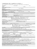
2 Thetransducer is threaded to screw onto a standard 1/4inch SAE Flare PRESSURE tap, and should be mountedon the suction line near the TEMPERATURE are three color-coded lead wires and the trans-ducer is polarized. NOTE:Improved Cable for PRESSURE Transducers PRESSURE Transducers Part Numbers 952740 (2m300psig), 952503 (5m 300psig), 953091 (2m150psig), 953092 (5m 150psig) now include animproved hermetic cable. Please note that the colorcode has has three different TEMPERATURE sensors fordifferent applications. All of them are solid statedevices that change electrical resistance in responsetoa change in air sensor (item # 952669) is most often used inthe discharge air stream of the evaporator. The sen-sor location should be chosen using the same criteriaas would be used for location of a thermostat. Heatsources such as lights and anti-sweat heaters, as wellas areas with poor air flow should be avoided.
3 Thesensor should be mounted in the air stream using aclip such as that pictured in figure surface sensor (item # 952662) is typicallymounted on the suction line, as close to the evapora-tor as possible using the wire ties included, see thediagram in figure 2. In the case of sensors used fortwo temperaturesuperheat control, one sensor ismounted on the liquid line at the inlet to the evapo-rator, and the other is mounted on the suction line atthe outlet of the evaporator. The well sensor (item # 952795) is used on suctionlines 7/8" or larger utilizes the same sensing elementas the surface sensor , but is provided with a wellis a specially designed brass fitting, whichis threaded into a 1/4" NPT hole or fitting in the suc-tion line. The sensor probe is inserted into the wellalong with the heat transfer grease. See figure sensors are generally used with iron pipewhich has very poor thermal transfer properties.
4 Besure to wrap the threads on the well fitting withTeflon tape or use some form of thread Kelvin sensor 952551 (white) can be mountedon the suction line for superheat control. Refer toFigure 2. For T2 air control mount sensor as shownin figure 1 in a location best suited for air tempera-ture Pigtail leadsNew HermeticCable1+ or 2+RedBlack1- or 2-BlackGreen1S or 2 SGreenWhiteHeat TransferGreasefigure 1figure 2figure 3 Neither the PRESSURE TRANSDUCER or TEMPERATURE sen-sor can be repaired. Using the charts below, meas-urements can be taken to assure that they arefunctioning correctly. If components are found to beout of tolerance, they should be (Degrees Farenheit)OhmsTemperature sensor Resistance200002000040000400000060000600 00800008000010 000010 0 0 0 0 10 00010 0 0 0 3000030000500005000070000700009000090000 110000110000-60-40-2002040608010 0120 1401602K Resistor3K ResistorPressure TRANSDUCER DC952740953091 COPYRIGHT2006 BYSPORLANVALVEDIVISIONPARKERHANNIFINSERV ICE INSTRUCTIONSAs mentioned above, the TEMPERATURE sensor changeselectrical resistance in response to temperaturechanges.
5 Disconnect the sensor from the controller,then check and record the resistance through the tem-perature sensor . Check the TEMPERATURE of the suctionline at the sensor location, and compare to the chartin figure 4. Example: at 0 F, the resistance throughthe TEMPERATURE sensor should be approximately10,000 Ohms. Reconnect the TEMPERATURE sensor tothe controller. TEMPERATURE SENSORPRESSURE TRANSDUCERThe output voltage of the PRESSURE transducerchanges in response to PRESSURE changes within thesystem. With the system running and using a DCvoltmeter, measure the voltage between the whiteand green lead wires from the TRANSDUCER . Removethe TRANSDUCER from its fitting, and replace itwith a union teewith a core depressor. Install thetransducer on one of the male fittings of the tee,anda PRESSURE gauge on the other.
6 Read the PRESSURE onthe gauge and compare the findings to the chart infigure 5. Example: at 50 PSI, the voltage between thetwo leads should be approximately VDC. Re-install the PRESSURE TRANSDUCER on the 4figure 5 Page 2 PRINTED OFA. SD-245-5-107 ResistanceColorPartNumber2kBlack95266995 26629527953kWhite952551