Transcription of Pressure Vessels Stresses Under Combined Loads Yield ...
1 OPTI 222 Mechanical Design in Optical Engineering 113 Pressure Vessels Stresses Under Combined Loads Yield Criteria for Ductile Materials and Fracture Criteria for Brittle Materials Pressure Vessels : In the previous lectures we have discussed elements subjected to plane stress where z = zx = zy = 0. thin - walled Pressure Vessels are one of the most typical examples of plane stress. When the wall thickness is thin relative to the radius of the vessel , plane stress equations are valid. In addition, since no shear Stresses exist, the state of stress can be further classified as a biaxial state of stress.
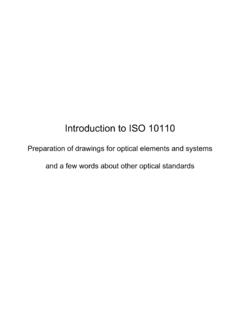
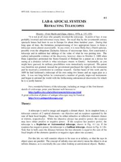
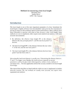
2 Spherical Pressure vessel Let s begin by considering a spherical Pressure vessel with radius r and wall thickness t subjected to an internal gage Pressure p . For reasons of symmetry, all the normal Stresses on a small stress element in the wall must be identical. Furthermore, there can be no shear stress. The normal Stresses can be related to the Pressure p by inspecting a free body diagram of the Pressure vessel . To simplify the analysis, we cut the vessel in half as illustrated. Since the vessel is Under static equilibrium, it must satisfy Newton's first law of motion. In other words, the stress around the wall must have a net resultant to balance the internal Pressure across the cross-section.
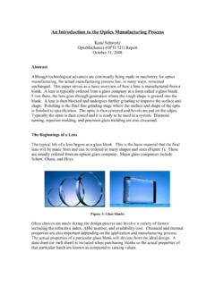
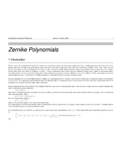
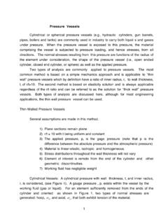
3 Summing forces we obtain: 2 rt = p r2 Solving for stress we obtain: 2prt = This normal stress is known as the axial, longitudinal or meridional stress. OPTI 222 Mechanical Design in Optical Engineering 114 Cylindrical Pressure vessel Now let s consider a cylindrical Pressure vessel with radius r and wall thickness t subjected to an internal gage Pressure p . The coordinates used to describe the cylindrical vessel can take advantage of its axial symmetry. It is natural to align one coordinate along the axis of the vessel ( in the longitudinal or axial direction). To analyze the stress state in the vessel wall, a second coordinate is then aligned along the hoop direction ( tangential or circumferential direction).
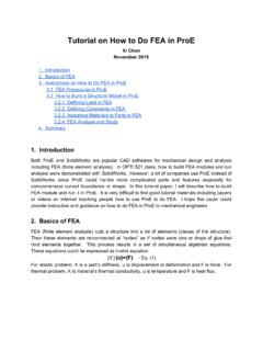
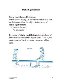
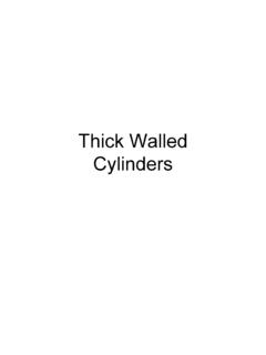
4 With this choice of axisymmetric coordinates, there is no shear stress. The hoop stress h and the longitudinal stress l are the principal Stresses . To determine the longitudinal stress l, we make a cut across the cylinder similar to analyzing the spherical Pressure vessel . The free body, shown on the next page, is in static equilibrium. This implies that the stress around the wall must have a resultant to balance the internal Pressure across the cross-section. Summing forces in the longitudinal direction we obtain the same result as with the spherical Pressure vessel . 2lprt = OPTI 222 Mechanical Design in Optical Engineering 115To determine the circumferential or hoop stress h, we make a cut along the longitudinal axis and construct a small slice as illustrated below.
5 Summing forces in the hoop direction we obtain: 2 htdx = p2rdx Solving for the hoop stress we obtain: hprt = In summary we have: Longitudinal Stress 2lprt = Hoop Stress hprt = Note: The above formulas are good for thin - walled Pressure Vessels . Generally, a Pressure vessel is considered to be " thin - walled " if its radius r is larger than 5 times its wall thickness t (r > 5t). When a Pressure vessel is subjected to external Pressure , the above formulas are still valid. However, the Stresses are now negative since the wall is now in compression instead of tension. OPTI 222 Mechanical Design in Optical Engineering 116 Stresses Under Combined Loads : To this point we have considered the response of members subjected to the separate effects of axial Loads , torsion, bending and uniform Pressure .
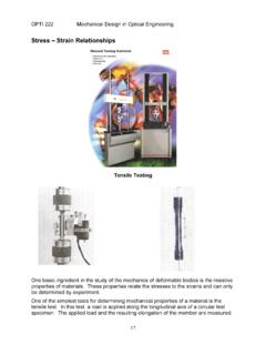
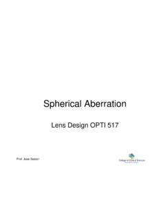
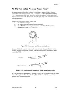
6 However, in many cases structural members are required to resist more than one type of loading. The stress analysis of a member subjected to Combined loadings can usually be performed by superimposing the Stresses due to each load acting separately. Superposition is permissible if the Stresses are linear functions of the Loads and if there is no interaction effect between the various Loads ( the Stresses due to one load are not affected by the presence of any other Loads ). Let s consider the following example. Torsion TrJ = 2,400 psi Bending (M1) 1MS = 14,400 psi Bending (M2) 2MS = 9,600 psi Axial PA = 200 psi Transverse Shear 43VA = 133 psi OPTI 222 Mechanical Design in Optical Engineering 117We can now combine the individual load cases to obtain the stress elements show below: Torsion TrJ = 2,400 psi Bending (M1) 1MS = 14,400 psi Bending (M2) 2MS = 9,600 psi Axial PA = 200 psi Transverse Shear 43VA = 133 psi OPTI 222 Mechanical Design in Optical Engineering 118 Failure Criteria.
7 The purpose of failure criteria is to predict or estimate the failure/ Yield of structural members subjected biaxial or triaxial states of stress. A considerable number of theories have been proposed. However, only the most common and well-tested theories applicable to isotropic materials are discussed here. These theories, dependent on the nature of the material in question ( brittle or ductile), are listed in the following table: Material Type Failure Theories Ductile Maximum shear stress criterion, Von Mises criterion Brittle Maximum normal stress criterion, Mohr s theory 1. Whether a material is brittle or ductile could be a subjective guess, and often depends on temperature, strain levels, and other environmental conditions.
8 However, a 5% elongation criterion at break is a reasonable dividing line. Materials with a larger elongation can be considered ductile and those with a lower value brittle. Another distinction is a brittle material's compression strength is usually significantly larger than its tensile strength. 2. All popular failure criteria rely on only a handful of basic tests (such as uniaxial tensile and/or compression strength), even though most machine parts and structural members are typically subjected to multi-axial loading. This disparity is usually driven by cost, since complete multi-axial failure testing requires extensive, complicated, and expensive tests.
9 Non Stress-Based Criteria: The success of all machine parts and structural members are not necessarily determined by their strength. Whether a part succeeds or fails may depend on other factors, such as stiffness, vibrational characteristics, fatigue resistance, and/or creep resistance. For example, the automobile industry has endeavored many years to increase the rigidity of passenger cages and install additional safety equipment. The bicycle industry continues to decrease the weight and increase the stiffness of bicycles to enhance their performance. In civil engineering, a patio deck only needs to be strong enough to carry the weight of several people.
10 However, a design based on the "strong enough" precept will often result a bouncy deck that most people will find objectionable. Rather, the stiffness of the deck determines the success of the design. Many factors, in addition to stress, may contribute to the design requirements of a part. Together, these requirements are intended to increase the sense of security, safety, and quality of service of the part. OPTI 222 Mechanical Design in Optical Engineering 119 Maximum Shear Stress Criterion: The maximum shear stress criterion, also known as Tresca's or Guest's criterion, is often used to predict the yielding of ductile materials.