Transcription of Pressurized Water Reactor (PWR) Systems - nrc.gov
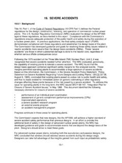
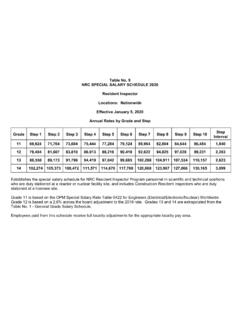
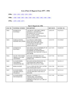
1 Reactor Concepts ManualPressurized Water Reactor SystemsUSNRC Technical Training Center4-10603 PressurizedWaterReactor (PWR) SystemsFor a nuclear power plant to perform the function of generating electricity, many different Systems mustperform their functions. These functions may range from the monitoring of a plant parameter to thecontrolling of the main turbine or the Reactor . This chapter will discuss the purposes of some of themajor Systems and components associated with a Pressurized Water Concepts ManualPressurized Water Reactor SystemsUSNRC Technical Training Center4-20603 CORES/GRCPAUXILIARY BUILDINGRHRHXCONTAINMENTSUMPCONTAINMENT BUILDINGPZRREACTORCOOLANT SYSTEMTURBINE BUILDINGFWHTRMSRHPLPMAINCONDENSERELECTRI CGENERATORCOOLING TOWERCIRC.
2 WATERPUMPRHRPUMPMAINTURBINECONDENSATEPUM PMAIN FEEDPUMPT here are two major Systems utilized to convert the heat generated in the fuel into electrical power forindustrial and residential use. The primary system transfers the heat from the fuel to the steam generator,where the secondary system begins. The steam formed in the steam generator is transferred by thesecondary system to the main turbine generator, where it is converted into electricity. After passingthrough the low pressure turbine, the steam is routed to the main condenser.
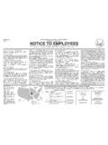
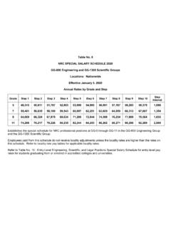
3 Cool Water , flowingthrough the tubes in the condenser, removes excess heat from the steam, which allows the steam tocondense. The Water is then pumped back to the steam generator for order for the primary and secondary Systems to perform their functions, there are approximately onehundred support Systems . In addition, for emergencies, there are dedicated Systems to mitigate theconsequences of Concepts ManualPressurized Water Reactor SystemsUSNRC Technical Training Center4-30603 PRESSURIZERREACTORSTEAMGENERATORREACTORC OOLANTPUMPThe primary system (also called the Reactor Coolant System) consists of the Reactor vessel, the steamgenerators, the Reactor coolant pumps, a pressurizer, and the connecting piping.
4 A Reactor coolant loopis a Reactor coolant pump, a steam generator, and the piping that connects these components to thereactor vessel. The primary function of the Reactor coolant system is to transfer the heat from the fuelto the steam generators. A second function is to contain any fission products that escape the following drawings show the layout of the Reactor coolant Systems for three Pressurized waterreactor vendors. All of the Systems consist of the same major components, but they are arranged inslightly different ways.
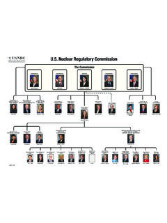
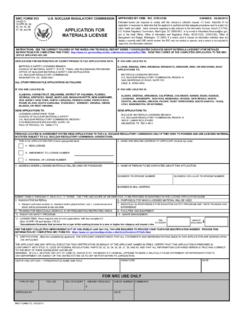
5 For example, Westinghouse has built plant with two, three, or four loops,depending upon the power output of the plant. The Combustion Engineering plants and the Babcock& Wilcox plants only have two steam generators, but they have four Reactor coolant Concepts ManualPressurized Water Reactor SystemsUSNRC Technical Training Center4-40603 REACTORCOOLANTPUMPPRESSURIZERSTEAMGENERA TORREACTORA two-loop Westinghouse plant has two steam generators, two Reactor coolant pumps, and a two-loop units in the United States are Ginna, Kewaunee, Point Beach 1 and 2, and Prairie Island1 and 2.
6 Each of these plants has 121, 14 x 14 fuel assemblies arranged inside a Reactor vessel that hasan internal diameter of 132 inches. The electrical output of these plants is approximately 500 Concepts ManualPressurized Water Reactor SystemsUSNRC Technical Training Center4-50603 STEAMGENERATORPRESSURIZERMAINCOOLANTPUMP REACTORA three-loop Westinghouse plant has three steam generators, three Reactor coolant pumps, and apressurizer. The three-loop units in the United States are Beaver Valley 1 and 2, Farley 1 and 2, H. 2, North Anna 1 and 2, Shearon Harris 1, V.
7 C. Summer, Surry 1 and 2, and Turkey Point 3and 4. Each of these plants has 157 fuel assemblies. Some units use 15 x 15 fuel assemblies whileothers use 17 x 17 arrays. The Reactor vessels have internal diameters of 156 to 159 inches, exceptSummer and Turkey Point, which have 172-inch Reactor vessels. The electrical output of these plantsvaries from almost 700 to more than 900 Concepts ManualPressurized Water Reactor SystemsUSNRC Technical Training Center4-60603 STEAM GENERATORMAIN COOLANT PUMPPRESSURIZERREACTORA four-loop Westinghouse plant has four steam generators, four Reactor coolant pumps, and apressurizer.
8 The four-loop units in the United States are Braidwood 1 and 2, Byron 1 and 2, Callaway,Catawba 1 and 2, Comanche Peak 1 and 2, D. C. Cook 1 and 2, Diablo Canyon 1 and 2, Indian Point 2and 3, McGuire 1 and 2, Millstone 3, Salem 1 and 2, Seabrook, Sequoyah 1 and 2, South Texas Project1 and 2, Vogtle 1 and 2, Watts Bar 1, and Wolf Creek. Each of these plants has 193 fuel assembliesarranged inside a Reactor vessel that has an internal diameter of 173 inches (except South Texas has aninternal diameter of 167 inches). The fuel assemblies are arranged in 17 x 17 array except for Cook andIndian Point, which have 15 x 15 fuel.
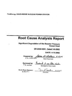
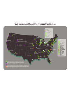
9 The electrical output of these plants ranges from 950 to Concepts ManualPressurized Water Reactor SystemsUSNRC Technical Training Center4-70603A Babcock & Wilcox plant has two once through steam generators, four Reactor coolant pumps, and apressurizer. The Babcock & Wilcox units in the United States are Arkansas 1, Crystal River 3, DavisBesse, Oconee 1, 2, and 3, and Three Mile Island 1. Each of these plants has 177 fuel assemblies. Theelectrical output of these plants is approximately 850 Concepts ManualPressurized Water Reactor SystemsUSNRC Technical Training Center4-80603 STEAMGENERATORNo.
10 1 PUMPNo. 1 BPUMPNo. 1 APUMPNo. 2 APUMPNo. 2 BSTEAMGENERATORNo. 2 REACTORVESSELPRESSURIZERA Combustion Engineering plant has two steam generators, four Reactor coolant pumps, and apressurizer. The Combustion Engineering units in the United States are Arkansas 2, Calvert Cliffs 1 and2, Fort Calhoun, Millstone 2, Palisades, Palo Verde 1, 2, and 3, San Onofre 2 and 3, Saint Lucie 1 and2, and Waterford 3. The electrical output of these plants varies from less than 500 to more than Concepts ManualPressurized Water Reactor SystemsUSNRC Technical Training Center4-90603 Reactor VesselThe Reactor core, and all associated support and alignment devices, are housed within the Reactor vessel(cutaway view on page 4-10).