Transcription of Preventing Neutral Circulating Currents when …
1 White Paper: DPNL-WP001-A1 August 11, 2011 _____ Copyright 2011 Mirus international Inc. 31 Sun Pac Blvd., Brampton, Ontario, Canada L6S 5P6. All Rights Reserved. Preventing Neutral Circulating Currents when Paralleling Generators Prepared by: Anthony (Tony) Hoevenaars, P. Eng President and CEO Mirus international Inc. Page 2 of 11 Mirus international Inc. [2011-08-11] 1-888-TO MIRUS DPNL-WP001-A1 ABSTRACT As electrical energy rates continue to rise and the need for secure and reliable electricity grows, many opportunities for distributed generation (DG) have appeared. Equipment used in these applications include diesel or natural gas generators, wind turbines, solar panels, microturbines and fuel cells to name a few. These and other applications, such as standby generation for critical loads, often require the need to parallel multiple generators or other DG sources with themselves or the utility supply.
2 Controlling Circulating Currents when paralleling generators in a power system that shares a common Neutral can be difficult. In any paralleling operation, it is extremely important that voltages produced by the generating equipment are as closely matched as possible. To properly match voltages, not only do the RMS values need to be similar but the instantaneous values, which are determined by the voltage waveshapes, should be similar as well. when this is not possible, as in paralleling of generators with different winding pitch configurations, Circulating Currents may appear in the common Neutral which bonds the wye connections of the generating sources. These Circulating Currents can cause overheating in the generator windings and false tripping of overcurrent protection equipment, particularly ground fault detection schemes.
3 These conditions are most troublesome in permanently connected parallel applications but can also be an issue during closed transition transfers in peak shaving or back-up generation applications. To reduce these Circulating Currents , which are usually triple frequency in nature, a uniquely wound, multiple coil reactor, such as Mirus GenLink Dissimilar Pitch Neutral Limiter (DPNL), can be very effective. The unique winding configuration of the GenLink will block the flow of Circulating current while introducing minimal effect on the short circuit impedance of the system. GENERATOR PITCHES, HARMONICS AND VOLTAGE WAVESHAPE Ideally, all generator sources would produce output voltage waveforms that were purely sinusoidal. Even with their best efforts however, generator manufacturers cannot reach this goal and therefore, generator voltages will always be somewhat distorted and contain harmonics.
4 Which harmonic numbers are present and their level of magnitude is related to how the voltage is being generated. In synchronous generators for example, the harmonic voltages generated are influenced by the particular winding pitch of the generator s alternator. Table 1 shows the pitch factors for synchronous generators of various pitch types. These pitch factors are multiplied by the respective harmonic fluxes to predict the harmonic voltages [2]. Since differently pitched machines have different pitch factors for each harmonic number, their harmonic voltages and voltage waveshapes will be different as well. Pitch Fund. 3rd 5th 7th 9th 2/3 4/5 5/6 6/7 Table 1: Pitch factor impact on harmonic voltage magnitudes in synchronous generators [1][2] Figure 1 provides examples of the line-to- Neutral voltages of two dissimilarly pitched generators, G1 and G2.
5 G1 generates a voltage with a slightly higher peak (typical of 5/6 pitch generators) while G2 generates a somewhat flat-topped voltage waveform (typical of a 2/3 pitch generator). when paralleled, these generators will produce a phase-to- Neutral voltage Page 3 of 11 Mirus international Inc. [2011-08-11] 1-888-TO MIRUS DPNL-WP001-A1 that reflects the instantaneous differences in the two voltages even when the RMS values are identical. Since this voltage passes three cycles in the time that the individual generator voltage passes a single cycle (the fundamental frequency), it is primarily triple frequency in nature (180 Hz on a 60 Hz system). Circulating Currents will appear as shown in Figure 2 and will also be predominantly triple frequency.
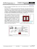
6 The amount of Circulating current intro-duced by each phase will be proportional to the magnitude of the differential instantaneous voltage for that phase and the zero phase sequence impedance of the system (generators and connecting cables). The total Circulating current in the common Neutral will be the sum of the Circulating current in each phase. Since the zero phase sequence impedance of the cables is normally quite small relative to that of the sources, it can typically be ignored. For the system shown in Figure 2 then, the Circulating current can be calculated using the following equation: )()(3212100,,GGGANGANNZZVVI+ = Equation 1 Figure 2: Flow of Circulating current in a 3-wire paralleled generator application with neutrals connected and ungrounded Figure 1: How differences in instantaneous voltages of paralleled equipment can produce line-to- Neutral voltages that result in Circulating Currents Page 4 of 11 Mirus international Inc.
7 [2011-08-11] 1-888-TO MIRUS DPNL-WP001-A1 It is important to note that it is not the generator s specific pitch value that causes the Circulating current but rather the difference in voltage waveshape of the two differently pitched generators. Therefore, the fact that a 2/3 pitch generator has a very low pitch factor for the 3rd harmonic does not mean that it will perform any better in paralleling operations. In fact, a 2/3 pitch generator has very low zero sequence reactance and therefore, has less impedance to reduce the flow of Circulating Neutral current [3]. Circulating Currents can result with any generator pitch type when it is not matched with a similarly pitched unit or it is paralleled with the Utility. Further complicating the issue is that this analysis has assumed that the generator loading is linear.
8 Today s power electronic loads (such as variable speed drives, computer equipment, AC/DC rectifiers, etc.) are nonlinear in nature and as such, are current sources of harmonics. During their operation, the current harmonics they draw will increase the voltage distortion throughout the distribution system. This includes the output terminals of the generator where the generator s source impedance (particularly the subtransient reactance or Xd ) will create voltage drops at each harmonic number in relation to the nonlinear load harmonic Currents [4]. These voltage drops will introduce additional harmonic distortion at the generator s output terminals. Differently pitched generators will have different impedances to the various harmonics and therefore, the differential voltage may be much greater than would be expected with linear loading.
9 TRADITIONAL METHODS OF TREATMENT The requirement to parallel generators is not new and therefore, Circulating Currents in the common Neutral is also not a totally new phenomenon. What has changed however is the frequency that these incidences are occurring as the use of DG equipment increases. One method of limiting Circulating Currents has been to ensure that all generators have the same pitch. This, of course, is not always possible or even preferred especially when expanding a site that has older, existing generators or where generators are being paralleled with the Utility. Another approach is to add impedance in the common Neutral . Standard reactors could be used for this purpose but any impedance added to reduce the Circulating Neutral current would also significantly reduce the single phase fault level in the system.
10 A slight reduction in fault level may be preferred in large systems where the fault level is initially high but normally the level of impedance required to suitably reduce the Circulating current will reduce the fault current to unacceptable levels. A fault level that is too low can be a serious safety concern since it can prevent overcurrent protection from operating and lead to fire hazards, such as arcing faults. Occasionally, an ungrounded system is employed where the generator neutrals are not connected together. In this scenario, there will be no path for the Circulating current to flow. There will also be no path for single phase fault Currents so ground fault monitoring and other measures used for ungrounded systems must be employed. GENLINK DISSIMILAR PITCH Neutral LIMITER (DPNL) The GenLink DPNL is a multiple winding reactor that is installed in the common Neutral of paralleled generators (see Figure 3) in order to add impedance to block the flow of Circulating Currents .