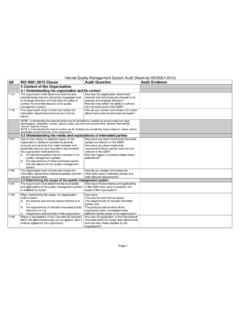
Transcription of Process Failure Mode and Effect Analysis
1 Example of Process Failure Mode and Effect Analysis By Pretesh Biswas (APB Consultant) Page1 Process Failure Mode and Effect Analysis Team Approach: The PFMEA is developed and maintained by a multi-disciplinary (or cross-functional) team typically led by the responsible engineer. During the initial development of the PFMEA, the responsible engineer/team leader is expected to directly and actively involve representatives from all affected areas. These areas should include but are not limited to design, assembly, manufacturing, materials, quality, service, and suppliers, as well as the area responsible for the next assembly. The PFMEA should be a catalyst to stimulate the interchange of ideas between the areas affected and thus promote a team approach.
2 Design Consideration: The team should assume the product as designed will meet the design intent. During the development of a PFMEA, the team may identify design opportunities which, if implemented, would either eliminate or reduce the occurrence of a Process Failure mode. For example, adding a feature to a part and a matching feature to a fixture will eliminate the possibility of an operator placing a part in the wrong orientation. Such information must be provided to the responsible design engineer as well as the tooling/equipment/fixture design-responsible individual for consideration and possible implementation. The Process -responsible engineer/team leader has at his or her disposal a number of documents that will be useful in preparing the PFMEA.
3 The PFMEA begins by developing a list of what the Process is expected to do and what it is expected not to do, , the Process intent. The PFMEA should begin with a flow chart of the general Process . This flow chart should identify the product/ Process characteristics associated with each operation. Identification of product effects from the corresponding DFMEA should be included. Copies of the flow chart used in the PFMEA preparation should accompany it. A Process flow diagrams describes the flow of the product through the Process from incoming to outgoing. This should include each step in a manufacturing or assembly Process as well as their related outputs (product characteristics, requirements, deliverables, etc.) and inputs ( Process characteristics, sources of variation, etc.)
4 The detail of the Process flow depends on the stage of Process development discussion. The initial flow diagram is generally considered a high level Process map. It needs more detailed Analysis to identify the potential Failure modes. High level to Detailed Process Map Example of Process Failure Mode and Effect Analysis By Pretesh Biswas (APB Consultant) Page2 The PFMEA should be consistent with the information in the Process flow diagram. The scope of the Process flow diagram should include all manufacturing operations from processing of individual components to assemblies including shipping, receiving, transportation of material, storage, conveyors, labeling, etc. A preliminary risk assessment using the Process flow diagram may be performed to identify which of these operations or individual steps can have an impact on the product manufacturing and assembly and should be included in the PFMEA.
5 The PFMEA development continues by identifying the requirement(s) for each Process /function. Requirements are the outputs of each operation/step and relate to the requirements for the product. The Requirements provide a description of what should be achieved at each operation/step. The Requirements provide the team with a basis to identify potential Failure modes. In order to assure continuity, it is highly recommended that the same cross-functional team develop the Process Flow Diagram, PFMEA, and Control Plan. Other sources of information that are useful in providing the team with ways to focus and capture discussions on the requirements of the Process include: DFMEA Drawings and design records Bill of Process Interrelationship (Characteristic) matrix Internal and external (customer) nonconformance ( , known Failure modes based on historical data) Quality and Reliability History After establishing the scope of the Analysis effort, the team should begin by reviewing historical information.
6 The areas to review should include: Lessons that have been learned from previous product and Process design implementation, and Any information available that establishes best practices including items such as guidelines and standards, standard part identification, or error-proofing methods. Quality performance information available from similar, previous product and Process designs, including items such as Process yield, first time capability (both end of line and at each operation), Pans per Million (PPM), Process capability indices (Cpk and Ppk), and warranty metrics. The information can be useful input for determination of severity, occurrence and detection rankings. Example of Process Failure Mode and Effect Analysis By Pretesh Biswas (APB Consultant) Page3 Sample PFMEA Form with Minimal Information Elements & Example Entries FMEA Number (A) Enter an alphanumeric string which is used to identify the FMEA document.
7 This is used for document control. System, Subsystem, or Component Name and Number (B). Enter the name and number of the system, subsystem, or component which is being analyzed. Example of Process Failure Mode and Effect Analysis By Pretesh Biswas (APB Consultant) Page4 Process Responsibility (C) Enter the OEM, organization, and department or group who is Process design responsible. Also enter the supply organization name, if applicable. Model Year(s)/Program(s) (D) Enter the intended model year(s) and program(s) that will use or be affected by the Process being analyzed (if known). Key Date (E). Enter the initial PFMEA due date, which should not exceed the scheduled start of production date. In case of a supply organization, this date should not exceed the customer required Production Part Approval Process (PPAP) submission date.
8 FMEA Dates (F) Enter the date the original PFMEA was completed and the latest revision date. Core Team (G) Enter the team members responsible for developing the PFMEA. Contact information ( , name, organization, telephone number, and email) may be included in a referenced supplemental document. Prepared By (H) Enter the name and contact information including the organization (company) of the engineer responsible for preparing the PFMEA. Body of DFMEA Form (Fields a-n) The body of the PFMEA contains the Analysis of risks related to the potential failures, and improvement action being taken. Process steps / Process Function /Requirements (a) Process Step/Function can be separated into two (or more) columns or combined into a single, bridged column which encompasses these elements.
9 Process Steps may be listed in the Process Step/Function column or additional column(s) may be added containing the functions or requirements of that Process step. Process Step , Function , and Requirements are described below: Process Step (a1) Enter the identification of the Process step or operation being analyzed, based on the numbering Process and terminology. For example, enter the number and identifier ( , name). Process numbering scheme, sequencing, and terminology used should be consistent with those used in the Process flow diagram to ensure traceability and relationships to other documents (Control Plans, operator instructions, etc). Repair and rework operations should also be included.
10 Example of Process Failure Mode and Effect Analysis By Pretesh Biswas (APB Consultant) Page5 Process Function (a1) List the Process function that corresponds to each Process step or operation being analyzed. The Process function describes the purpose or intent of the operation. A risk Analysis is recommended in order to limit the number of steps to be included to only those that add value or otherwise are seen as likely to have a negative impact on the product. If there are multiple Process functions being analyzed with respect to a given operation, each should be aligned on the form with its respective Requirements to aid in the development of the associated Failure modes. Process Function becomes a2 if Process Step and Process Function are split.