Transcription of Process isolation – it’s more complicated than you think
1 Loss Prevention Bulletin 231 June 2013 | 19. Safety practice Process isolation it's more complicated than you think Andy Brazier, AB Risk Limited depending on the duty of the plant and the task being Summary performed. It formalised the use of double block and bleed,'. Properly planned and implemented isolations are required pointing out that valve integrity needs to be proven if an to provide a barrier between the plant/equipment being isolation is to be relied upon. worked on and the sources of the hazardous substances The original OIAC document has been updated and and conditions. These isolations are usually achieved published by HSE as Health and Safety Guidance Document in the first instance by closing valves, but more robust (HSG) 2531 and many companies have developed their own, methods may be required depending on the nature of in-house isolation standards. It appears that in the years since the hazard and the work to be carried out.
2 Unfortunately, 1997 the HSE have accepted industries suggestions and isolation procedures adopted by some companies are converted them into requirements. Also, companies agreed to not fully up to the expected standard. In particular, many comply. people do not properly understand the sequence of Given that the requirements have been clear for some time steps required to prove valve integrity and are content as and accepted by industry it would be reasonable to assume long as the correct valves are closed and secured before that compliance has been achieved; but experience has shown beginning work. that companies' isolation procedures often fall short of the This article reminds readers that Process isolation requirements, particularly for proving the integrity of valves. is not necessarily as straightforward as expected and Also, people often do not fully understand why adherence to runs through the steps to achieve correct and proven a strict sequence of steps is required when isolating plant and isolations.
3 Equipment. Keywords: Process isolation , valve integrity An interesting' example Isolating a pig receiver in preparation for opening the door Introduction provides an excellent example to demonstrate the potential Process plant and equipment will often contain hazardous difficulties in achieving a suitable isolation . It is universally substances and conditions. If intrusive work has to be carried accepted as a critical activity requiring a high degree of out, typically maintenance, there is a chance that hazards integrity. The sketch below demonstrates that the receiver may be released that cause harm to people in the vicinity. In will need to be isolated from the pipeline at both its inlet and order to reduce the risks, properly planned and implemented in its kicker line. Given that the pipeline is likely to be live isolations are required that provide a barrier between the and possibly at high pressure, there can be no doubt that a source of the hazard and the plant or equipment being worked proven isolation will be required.
4 A double block and bleed on. These isolations are usually achieved in the first instance by arrangement can be used for this. closing valves, but more robust methods may also be required A level of complexity is introduced when we recognise that such as inserting spades or removing pipework depending on there is more to the isolation than simply shutting valves. In the nature of the hazard and the work to be carried out. Also, this case the receiver will need to be depressurised, drained, part of the isolation procedure includes removing any hazard purged and vented. Closed vent and drain systems are contained within the equipment, which may require draining, often required so that hazardous material can be removed venting and/or purging with an inert substance. in a safe way. These create additional Process connections In 1997 a document was published titled The Safe isolation that require isolation . A further complication is created by of Plant and Equipment.
5 ' Whilst endorsed by the Health and overpressure protection provided by a relief valve connected Safety Executive (HSE), it had actually been developed by to the vent header. This will need to be isolated, but should the Oil Industry Advisory Committee (OIAC). In other words, remain available for as long as possible to ensure protection is the regulator was not telling industry how to isolate plant and provided. equipment, and instead industry was explaining what it did (or The sequence of steps required to isolate this pig receiver at least what it thought it should do). is summarised below. It should be noted that this is actually a The original document set out a method for determining simplified scenario because in reality there may be additional what form of isolation should be used ranging from single items to consider including a balance line, multiple drain points valve through to positive isolation ' using spades and blanks and purge connections.
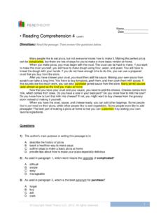
6 Institution of Chemical Engineers 0260-9576/13/$ + 19 30/05/2013 15:32. 20 | Loss Prevention Bulletin 231 June 2013. Emergency vent header Process vent header 1st 2nd Kicker line isolation 2nd 1st 2nd 1st Pig receiver Pipeline isolation 1st 2nd Closed drain Sequence of events 8. Confirm no pressure is present if pressure is present it indicates that the first isolation valve (closest to the The sequence of steps followed to isolate the pig receiver can pig receiver) has passed. be summarised as follows: 9. Open bleed valve to complete the double block and Drain, vent and purge the receiver; bleed isolation between pig receiver and closed Prove the integrity of isolations. drain system. How complicated can that be? This sequence of steps is clearly achievable but is reliant on the operator to understand how the integrity of the valves can Drain the receiver be proven. A pressure gauge located between the isolation To drain the receiver we will usually want pressure to force valves can make this easier.
7 However, they are not always liquids through to the closed drain system. There is no reason available, which means the operator has to be quite alert to why we need to isolate from the pipeline to do this. Therefore detect pressure when proving the second isolation valve and our first step can be: lack of pressure when proving the first isolation valve. However, there is a potentially fundamental problem with 1. Open two drain valves. the proposed sequence of events it only tests the integrity of It is somewhat ironic that we will start our isolation by the isolation valves in the direction from the pig receiver to the removing the existing isolations on the pipework between closed drain system. When we open the receiver we actually the receiver and closed drain system, but this is unavoidable. want protection against a pressure in the closed drain system Once we are happy that draining is complete we can close ( the opposite direction).
8 The problem is that the pressure those valves, but we need to think about how we can prove in the closed drain system will normally be far less than its their integrity. potential, which means there is not a readily available source A double block and bleed isolation will normally be of pressure to prove valve integrity in the correct' direction required on the pipework to the closed drain system because from closed drain to pig receiver. of the high pressure inside the pig receiver. This provides us There are ways of proving the integrity of the first isolation with the opportunity to prove the integrity of the two block valve in this direction. They include: valves as follows: Leave the space between the isolation valves pressurised 2. Shut both drain valves. until after the pig receiver has been depressurised. This 3. Leave for a short time. will require the first isolation valve to be reopened and closed after its initial integrity check.
9 4. Confirm pressure is present between the isolation valves if there is no pressure it indicates that the Use an external source to pressurise the space between second isolation valve (furthest from the pig receiver) the isolation valves. Nitrogen from a utility system or has passed. cylinders would be suitable for this. 5. Open the bleed valve to vent pressure. Proving integrity of drain valves in both directions is not straightforward and is probably easy to overlook; and on a 6. Reclose the bleed valve. standard double block and bleed isolation on a closed drain 7. Leave for a short time. system, it is not actually possible to prove the integrity of the Institution of Chemical Engineers 0260-9576/13/$ + 20 30/05/2013 15:32. Loss Prevention Bulletin 231 June 2013 | 21. second isolation valve in the correct direction. has not yet been proven. The following sequence of steps will allow the isolation to be completed whilst proving valve Prepare to depressurise the receiver integrity: At this stage, the receiver has been drained but is open to the 23.
10 Leave the receiver for some time and monitor pressure pipeline. It needs to be depressurised to the vent header. To if pressure builds up it indicates that the first isolation prepare for this it is necessary to isolate it from the pipeline, valve from pipeline or on kicker line has passed. but the sequences of steps must allow us to prove valve integrity. The following steps should be completed: 24. Shut second isolation valve on pipeline (furthest from receiver). 10. Shut first isolation valve on pipeline (closest to receiver); 25. Shut second isolation valve on kicker line (furthest 11. Shut first isolation valve on kicker line (closest to from receiver). receiver). 26. Open the bleed valve between pipeline isolation valves to vent pressure. Depressurise the receiver The sequence of steps followed when depressurising the 27. Reclose bleed valve. receiver has to allow valve integrity to be proven. This can be 28. Leave for a short time.