Transcription of PROCESSING AND TECHNICAL DATA - ALUCOBOND
1 PROCESSING AND TECHNICAL DATA. Simply original, originally simple 1. CONTENTS. TRANSPORTATION, STORAGE. 4 General PANEL DIMENSIONING. 5 General PANEL INSTALLATION. 6 General INFORMATION ON SPECIAL SURFACES. 7 Anodised, naturAL, mill-finished surfaces PROCESSING METHODS. 9 Sawing 11 Routing 12 Water jet cutting 12 Punching / shearing 13 Bending ROUTING AND FOLDING TECHNIQUE. 15 General 16 Machines 17 Tools 19 Fabrication of tray panels 21 Fabrication of attica corners 90 in two segments JOINTING / FIXING TECHNIQUE. 24 General 24 Thermal expansion and contraction 25 Drilling / countersinking 26 Riveting 27 Screwing 28 Gluing 31 Clamping SURFACE TREATMENT. 32 General CLEANING AND MAINTENANCE. 33 General 33 Removal of graffiti FACADE - STANDARD DESIGNS. 35 General TECHNICAL DATA SHEETS. 37 ALUCOBOND PLUS. 38 ALUCOBOND A2. INTERNET ADDRESSES, INFORMATION, CREATE THE DIFFERENCE. 40 Internet addresses 42 Information 43 Create the difference Edition 3 ALUCOBOND PROCESSING and TECHNICAL Data GB 3.
2 TRANSPORTATION, STORAGE. GENERAL. To protect ALUCOBOND composite panels against mechanical d amages m m and the harmful effects of weather conditions and moisture, the following information must be observed: -- The pallets must be handled carefully during transport and unloading. (Caution: Do not handle open pallets). Set maximum fork width -- Upon delivery the pallets must be examined for any damage due to transportation and moisture -- ALUCOBOND panels that have become wet must be dried to avoid any spots or corrosion forming. Any damage must be reported imme- diately and confirmed by the forwarding agent. -- Store the pallets so that they are protected against any wetness penetrating due to rain and spray water and avoid any condensation forming ( when transporting cold panels to warmer rooms). Pick up the pallet, slightly raise the fork -- Store the pallets stacked one over the other (do not store A. LUCOBOND . panels standing vertically) with a maximum of 6 pallets of the same format stacked on top of each other (heavy pallets at the bottom).
3 -- Individual panels must be lifted off the pallet by two people holding all four corners and not drawn over each other. Carry the panels vertically. Wear gloves to avoid staining. -- When stacking panels, nothing should be put in between to avoid markings. Pick up the complete pallet, do not draw nor push To ensure perfect functioning of the ALUCOBOND protective film, the following information should be observed: -- Storage exceeding 6 months should be avoided. Severe temperature fluctuations and exposure to direct sunlight reduce the long-term durability. In this case the protective film may become very difficult to remove. -- Do not mark the protective film with inks (markers), tapes or labels. Solvent or plasticizer may penetrate the film and affect the lacquered surface. -- Should the protective film partially come off during PROCESSING or after assembly, dirtied edges can occur in the course of time, which may be difficult to remove. -- Remove the protective film as soon as possible after assembly.
4 P rotective film that remains on the panels for an extended period of exterior exposure may be very difficult to remove. -- Make sure not to remove the protective film at temperatures below 10 C. 4 Edition 3 ALUCOBOND PROCESSING and TECHNICAL Data GB. PANEL DIMENSIONING. WHEN DIMENSIONING THE PANELS, THE FOLLOWING SHOULD. BE NOTED. Dimensional tolerances (Standard). Due to manufacturing, a displacement of the cover sheets sidewise at the panel edges up to 2 mm is possible. Thickness mm (mill-finish | stove lacquered | anodized). Width -0 / +4 mm Length 2000 4000 mm -0 / +6 mm Length 4001 6800 mm -0 / +10 mm When cutting and routing, the thermal expansion in length of ALUCOBOND . must be taken into account to ensure the dimensional accuracy of the components during assembly. We recommend that prior to PROCESSING the panels should be stored at room temperature for at least one day. Trimming The panels have to be trimmed: -- on all sides, to ensure accurate rectangularity and precisely cut edges when using raw edges, such as with the riveted fa ade version.
5 -- on three sides, to ensure accurate rectangularity for further PROCESSING . The trimming cuts must be taken into account when dimensioning the panel. Anodised contact lines Anodised ALUCOBOND composite panels have contact lines on the short sides of up to 25 mm width on the front and up to 35 mm width on the back. With panel lengths of more than m, contact lines of up to 20 mm width must also be taken into account at the longitudinal edges. Panel edges Due to the manufacturing process a lateral displacement of the cover sheets of max. 2 mm is possible at the panel edges. Static calculation of elements -- For static values, please see the TECHNICAL Data Sheets -- For static tables, please ask for details Edition 3 ALUCOBOND PROCESSING and TECHNICAL Data GB 5. PANEL INSTALLATION. WHEN INSTALLING THE PANELS, THE FOLLOWING SHOULD BE. NOTED. Assembly direction To avoid possible refl ection differences (for metallic, special effect, naturAL, and Spectra colours), we recommend that the composite panels should be installed in the same direction as marked on the protective fi lm.
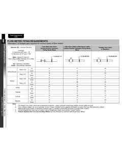
6 Protective fi lm with direction arrows Colour variations may occur between panels originating from different production batches. To be sure of homogeneous colouring, the total requirement for a project should be ordered in one batch, the front of a building should be composed of panels of one batch only (see pallet label or stamp on the reverse side). 3 Com 3A o po om pos osite t s Gm bH. te Alusingen-Platz 1. 78224 Singen Germ r any rm Batch No. on the reverse side Batch No. on the pallet label Fixing elements without jamming Linear expansion coeffi cient of ALUCOBOND mm/m/100 C. - The minimum gap depends on the expected expansion of the panel - Larger hole diameters in the panel must be taken into account when fi xing the panel with screws and rivets - Holes in the panel and in the substructure must be drilled centrically (use drilling jigs). - Distance between panel and rivet head mm (use rivet attachment jigs). - Be careful not to over-tighten the screws on the panel - Arrange the butt joints of the supporting sections at the panel joints to avoid jamming due to opposing thermal expansion Hole in the substructure SP SP.
7 Hole in the panel Centrical drilling FP FP. Fixed points and sliding points on the sub structure - For fi xing the supporting sections, pay attention to fi xed point holders (FP) and sliding point holders (SP). - Joints in the substructure must be taken into account when fi xing SP SP facade elements. They must not be skipped, the fa ade elements must not be f i xe d to the lowe r or uppe r suppor ting se ction! Butt joint of supporting section = panel joint 6 Edition 3 ALUCOBOND PROCESSING and TECHNICAL Data GB. INFORMATION ON SPECIAL SURFACES. Anodised surfaces During the anodising process an artificial oxide layer is produced on the aluminium surface. This takes place in a liquid medium with a defined bath composition under direct and alternating current. Anodized aluminum parts are used for a great range of exterior and inte- rior applications due to their corrosion resistance and decorative effect for. Even over prolonged periods (> 30 years), the layer of oxidation is only minimally reduced and the protective effect of anodically gener- ated oxide layers is not impaired.
8 These properties, however, are only retained for a longer period, if a sufficiently thick oxide layer has been built up and is well compacted on an aluminium material that is suitable for anodising. Additionally, the elements must be cleaned in such a way that the corrosive impact is also taken into account. According to DIN 17611, anodised ALUCOBOND and ALUCOBOND PLUS. composite panels are anodised, semi-finished products made of aluminium with an anodised layer thickness of at least 20 m for exterior a pplications. Quality assurance during the production of the panels according to DIN EN ISO 9001, ensures a high-quality, final product. Bending and folding anodized panels can result in micro cracks and fading may occur in that area. If this is not desired, enamelled ALUCOBOND . anodized look composite panels, whose surfaces comply with the anodiz- ing industry standard EURAS, can be folded or bent without problems. naturAL surfaces 3A Composites has introduced an innovative coating ALUCOBOND .
9 NaturAL that permanently preserves the natural, aluminium surface. During the rolling process this allows brushed structures to be produced, for example, with a clearly higher surface brilliance than we know of s tainless steel. The surface is not only weather-resistant but also insensitive to perspira- tion (finger prints). Cleaning only need occur in more regular intervals in highly corrosive environments ( near the coast or in industrial environments). In most cases, clean water will then be sufficient for cleaning and will prevent accumulation of salt or any other pollutants. Owing to the production process, ALUCOBOND naturAL Reflect p roduces a slightly iridescent effect in artificial light. Therefore, for interior a pplications please inquire a Reflect surface with a modified structure may be advisable. Due to the high degree of reflection of the underlying surface as compared to conventionally pigmented lacquer- ing the coating is exposed to almost double the UV radiation.
10 For this reason, the resistance of ALUCOBOND naturAL surfaces is reduced in the case of inclined planes and applications between latitudes of 20 N and 20 S. Edition 3 ALUCOBOND PROCESSING and TECHNICAL Data GB 7. INFORMATION ON SPECIAL SURFACES. Mill-finished surfaces When using ALUCOBOND panels with mill-finished surfaces that are not protected from atmospheric influences through coating or anodising, a variation in the appearance of the aluminium surface must be taken into account. The untreated, mill-finished aluminium surface on which no decorative demand should be made, acquires a natural oxide layer; in the course of time the thickness increases to approx. m under the influence of the outer atmosphere. When coated with reaction products, the surface shows a reduced reflectivity compared to its state when new, the surface loses its metallic brilliance taking on a dull, light-grey appearance. This impression may be intensified when dirt gathers in and on the surface.