Transcription of Processing Gain in Spread Spectrum Signals.
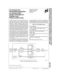
1 1 Processing gain in Spread Spectrum FakatselisHarris Box 883, Melbourne, FL. 32902-0883 ABSTRACTThis paper addresses the Processing gain (PG) characteristics of Spread Spectrum Systems. PGprovides some unique properties to the Spread Spectrum waveforms that can primarily improveperformance in the area of interference tolerance. The paper describes the benefits ofprocessing gain and the reasons that the PG properties have been attractive for both military andcommercial applications. It describes the signal Processing required to implement such systemsfor Direct Sequence (DS), Frequency hop, and Hybrid Spread Spectrum Systems. The papergives examples of applications that use the PG properties in communications systems. Anoverview of the maturity and the state of the art of presently available Spread Spectrumtechnology is also INTRODUCTION.
2 Processing gain (PG) is a term used todescribe one of the unique properties of SpreadSpectrum Waveforms. PG helps to measurethe performance advantage of Spread spectrumagainst narrowband waveforms. Spreadspectrum waveforms are modulated by using traditional modulation techniquessuch as PSK, FSK, etc. and then, for a secondtime with the wideband modulation of choice, Frequency Hopping (FH), Direct Sequence(DS) or Hybrid (FHDS). The widebandmodulation tends to Spread the signal energyover a wide range of frequencies. Thewideband modulation is what provides the basisfor the PG in Spread Spectrum systems. Spread Spectrum is being used because of anumber of attractive properties.
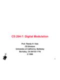
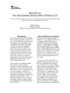
3 Spreadspectrum techniques had originally appealed tomilitary systems applications. These attractiveproperties are partially attributed to the are used to improve: Anti-jamming performance. Low probability of intercept, and Multiple Access communications. Commercial applications have adapted spreadspectrum technology and they can extractparallel benefits. These are: Interference immunity. Low transmit power density. Multiple simultaneous Processing gain FOR FHSYSTEMS. A Frequency Hop (FH) system obtains itswideband modulation characteristics byswitching its narrowband signal over a widerange of frequencies in time. Figure 1 illustratesan example of a transmission for a FH is a 3- dimensional figure with thehorizontal axis being Time the y-axis beingfrequency and the z-axis being amplitude.
4 As itis shown during FH the narrowband signal is hopping from frequency-to-frequency overtime. The narrowband signal is typicallymodulated using FSK modulation techniquevariations. For a Frequency Hop system the PG is definedas the ratio between the instantaneous BW ofeach hop (narrowband signal) and the overallBW of the transmission channel in dB. The FHsystem avoids narrowband interference bycontinuously hopping to a new instantaneousfrequency. The FH receiver is impacted by theinterferer only when the signal happens to hopat the same frequency with the interferer. This is best illustrated in Figure 1. Theinterference area of coverage is overlayed onthe 3- dimensional diagram that shows the FHtransmission example.
5 As shown on Figure 1,there are only three hop frequencies that havebeen impacted by the presence of theinterference. The rest of the frequencies areinterference free and the communications takeplace uninterrupted. It is obvious from theexample that the more instantaneous2frequencies are used and the wider the overallfrequency BW is, the greater interferenceimmunity is realized. This is because the signalspends less overall time on frequencies affectedby interference. One observation is that FHwaveforms can potentially avoid all together thefrequencies covered by interference and use theremainder. Conceptually is a valid possibilitybut regulatory bodies require mandatory usageof all frequencies in a random fashion.
6 This isto maintain a reduced average power densityover all the frequencies used in the Processing gain FOR DSSYSTEMS. For a DS system, random binary data with a bitrate of rb bits per sec (bps) is multiplied(Exclusive Or d) by a pseudorandom binarywaveform, which is at much higher rate and itprovides the frequency spreading pseudorandom (PN) binary source outputssymbols called chips at a constant chip rate rcchips per sec (cps). This is a random noise likesignal and hence the name PN signal. The chiprate is always higher than the bit rate, and theratio of the chip rate to the bit rate in dB isdefined as the Processing gain . The PG can beviewed as signal to jammer (interference) ratioat the receiver after the despreading operation(removal of PN).
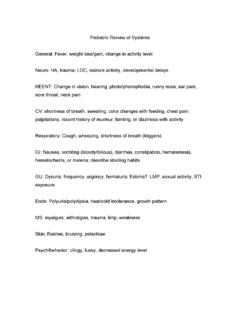
7 The larger the overall BW used, the higher thePG assuming a constant data rate. A higher PGimplies greater immunity against signals can actually operate at negativesignal to noise ratios given that they possessenough Processing gain . The typical primary modulation for a DS signalis of the PSK variation. If for example thenarrowband PSK requires an Eb/No of 12 dB toachieve a certain bit error rate performance,then a DS modulated PSK signal with a PG of20 dB requires an Eb/No of -8 dB (12dB-20dB).One trade-off that must be carefully worked outis that of total BW vs. PG. The greater the BWthe more total interference can potentially beinterfering with the DS 2 illustrates the concept of processinggain for DS waveforms as seen at the receiverend.
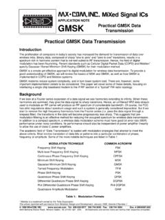
8 The unspread signal is the narrowbandPSK signal before applying the widebandmodulation. The Spread signal is with theaddition of the wideband modulation utilizing thePN code. It is apparent that the Spread signal iswider in frequency BW but with lower powerspectral density per Hz. The Spread signal isactually shown to be close to the noise for a DS system can be visualized as thejamming margin that exists as the differencebetween the unspread and Spread 1. FH Waveform in the Presence of RECEIVER FILTERFILTERUNSPREADUNSPREADSIGNALSIGNAL SPREADSPREADSIGNALSIGNALPROCESSINGPROCES SINGGAINGAINNOISENOISEF igure 2. DS Processing gain concept at the primary benefit of Processing gain is itscontribution towards interference PN code spreads the transmitted signal inbandwidth and it makes it less susceptible tonarrowband interference within the Spread receiver of a DS system can be viewed asunspreading the intended signal and at thesame time spreading the interfering operation is best illustrated on Figure 3.
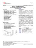
9 Figure 3 depicts the power spectral densityfunctions of the signals at the receiver input, thedespread signal, the bandpass filter powertransfer function, and the band pass filteroutput. Figure 3 graphically describes the effectof the Processing gain on a jammer. Theinterference (jammer) is narrow, and has ahighly peaked psd, while the psd of the DS iswide and low. The despreading operationspreads the jammer power psd and lowers itspeak, and the BPF output shows the effect onthe signal to jammer ratio. If for example, BPSK modulation is used andan Eb/No of lets say 14 dB is required toachieve a certain BER performance when thiswaveform is Spread with a Processing gain of 10dB, then the receiver can still achieve itsrequired performance with the signal having a4dB power advantage over the is derived from the 14dB required minusthe 10 dB of PG.
10 The higher the Processing gain of the DSSS waveform the more the resistance tointerference of the DS signal. The classical definition of Processing gain isthe10 Log[rc /rb] in dB. By this definition asystem that has a data rate of 10 MBPS and achip rate (rate of PN code) of 11 MCPS will havea PG of (f)+Sj(f)Tc/2fcJammer psdSpread Spectrum signalpsdfcTb/2 JTc/2Sx'(f)fcf1|H(f)|2fcfSy(f)Tb/2 JTc/2 JammerSignala) Psd of Spread Spectrum Signal andNarrowband JammerDespread JammerDespread Signalb) Psd of Despread Signal and JammerC) Power transfer function of BPFd) Psd of BPF outputFig. 3 Processing gain Effect on Narrow Band JammingIV. PG USING THE PRISMTM Harris Semiconductor has developed a state ofthe art DS radio chip set, the PRISMTM whichimplements the concept of PG.