Transcription of Product Bulletin DVC6200 Digital Valve Controller ...
1 FIELDVUE DVC6200 Digital ValveControllerThe FIELDVUE DVC6200 Digital Valve Controller is aHARTr communicating instrument that converts atwo wire 4 20 mA control signal into a pneumatic outputto an actuator. It can easily be retrofitted in place ofexisting analog positioners on most Fisher and non Fisherpneumatic Linkage Less Non Contact Position Feedback Thehigh performance, linkage less feedback systemeliminates physical contact between the Valve stemand the DVC6200 . There are no wearing parts so cyclelife is Built to Survive The field proven DVC6200 has fullyencapsulated electronics that resist the effects ofvibration, temperature, and corrosive atmospheres. Aweather tight wiring terminal box isolates field wiringconnections from other areas of the Actuator Overpressure PreventionPerformancen Accurate and Responsive The two stage positionerdesign provides quick response to large step changesand precise control for small setpoint Travel Control/Pressure Fallback Valve positionfeedback is critical to the operation of a Digital valvecontroller.
2 The DVC6200 can detect position feedbackproblems and automatically revert to pressure controlmode to keep the Valve Ramped Cutoff provides smooth transition fromthrottling control to shutoffEase of Usen Enhanced Safety The DVC6200 is a HART communicating device, so information can beaccessed anywhere along the loop. This flexibility canLINKAGE LESSFEEDBACK SYSTEMW9616reduce exposure to hazardous environments andmake it easier to evaluate valves in hard to Faster Commissioning HART communications allowsyou to quickly commission loops with a variety oftools, either locally at the Valve assembly or Easy Maintenance The DVC6200 is modular indesign. Critical working components can be replacedwithout removing field wiring or pneumatic Hardware Savings When installed in an integratedcontrol system, significant hardware and installationcost savings can be achieved.
3 Valve accessories suchas limit switches and position transmitters can beeliminated due to the integrated position transmitteror switch Increased Uptime The self diagnostic capability ofthe DVC6200 provides Valve performance and healthevaluation without shutting down the process orpulling the Valve assembly from the Improved Maintenance Decisions Digitalcommunication provides easy access to the conditionof the Valve . Sound process and asset managementdecisions can be made by analysis of Valve informationthrough Fisher ValveLink Digital Valve ControllerD103415X012 Product : DVC6200 September 2018 DVC6200 Digital Valve ControllerD103415X012 Product : DVC6200 September 2018 2 Figure 1. Condition IndicatorsERROR(RED CONDITION INDICATOR)WARNING(YELLOW CONDITION INDICATOR)E1208E1209 EVENT LOG PROVIDES POSSIBLE CAUSES ANDRECOMMENDED CORRECTIVE ACTIONSE1210 Valve DiagnosticsThe DVC6200 Digital Valve Controller provides a broadand deep portfolio of Valve diagnostic the 475 Field Communicator is used to checkfor Valve alerts and operational status, or ValveLinksoftware is used for comprehensive diagnostic test andanalysis, the tools are easy to use.
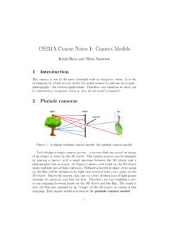
4 When installed as partof a HART communicating system, the DVC6200 deliversprompt notification of current or potential equipmentissues and supports NAMUR NE107 alert Diagnostics enable condition andperformance monitoring of the entire Valve assembly(not just the Digital Valve Controller ) while the Valve isactively controlling the process. When conductingPerformance Diagnostics tests, the Valve does NOT movebeyond the normal setpoint changes driven by theprocess Controller . The DVC6200 uses statisticalalgorithms to determine condition and performancerelated issues based on live readings from the manyon board sensors. Results are then displayed graphically,with severity indicated by a red/yellow/green indicator(figure 1).
5 A detailed description of the identified issue aswell as suggestions for recommended actions of identifiable issues are:n Low or high air supply or pressure droopn Incorrect regulator settingn Dirty air supplyn External air leak (actuator diaphragm or tubing)n Calibration shiftn Valve stuckn Piston actuator O ring failuren Excessive or insufficient Valve assembly frictionn Excessive Valve assembly deadbandn Elastomer failure in the DVC6200n Broken actuator springPerformance Diagnostics also provide access tofull stroke dynamic testing of the Valve assemblyincluding; Valve signature, dynamic error band, stepresponse, and stroke check. These tests change theinstrument setpoint at a controlled rate and areperformed while the Valve assembly is isolated from additional information on FIELDVUE diagnostics andValveLink software refer to Fisher Bulletin :ValveLinkSoftware (D102227X012).
6 DVC6200 Digital Valve ControllerD103415X012 Product : DVC6200 September 2018 3 SpecificationsAvailable MountingJIntegral mounting to Fisher 657/667 or GX actuatorsJIntegral mounting to Fisher rotary actuatorsJSliding stem linear applicationsJQuarter turn rotary applicationsDVC6200 Digital Valve controllers can also be mountedon other actuators that comply with IEC 60534 6 1, IEC 60534 6 2, VDI/VDE 3845 and NAMUR ProtocolJHART 5 or JHART 7 input SignalPoint to input Signal: 4 20 mA DC, nominal; split rangingavailableMinimum Voltage Available at Instrument Terminalsmust be VDC for analog control, 10 VDC for HART communicationMinimum Control Current: mAMinimum Current w/o Microprocessor Restart: mAMaximum Voltage: 30 VDCO vercurrent protectedReverse Polarity protectedMulti dropInstrument Power: 11 to 30 VDC at 10 mAReverse Polarity protectedSupply Pressure(1)Minimum Recommended: bar (5 psig) higher thanmaximum actuator requirementsMaximum.
7 Bar (145 psig) or maximum pressurerating of the actuator, whichever is lowerSupply MediumAir or Natural GasSupply medium must be clean, dry, and noncorrosiveand meet the requirements of ISA Standard orISO 8573-1 Output SignalPneumatic signal, up to full supply pressureMinimum Span: bar (6 psig)Maximum Span: bar (140 psig)Action: JDouble, JSingle Direct or JReverseSteady State Air Consumption(2)(3)At bar (20 psig) supply pressure: Less than normal m3/hr (14 scfh)At bar (80 psig) supply pressure: Less than normal m3/hr (49 scfh)Maximum Output Capacity(2)(3)At bar (20 psig) supply pressure: normal m3/hr (375 scfh)At bar (80 psig) supply pressure: normal m3/hr (1100 scfh)Operating Ambient Temperature Limits(1)(4)-40 to 85_C (-40 to 185_F) -52 to 85_C (-62 to 185_F) for instruments utilizing theExtreme Temperature option (fluorosiliconeelastomers)Independent Linearity(5)Typical Value: of output spanElectromagnetic CompatibilityMeets EN 61326 1:2013 Immunity Industrial locations per Table 2 of the EN 61326 1 standard.
8 Emissions class A ISM equipment rating: Group 1, class AVibration Testing MethodTested per ANSI/ISA Section ImpedanceAn equivalent impedance of 550 ohms may be value corresponds to 11V @ 20 Testing MethodTested per IEC 61514 2 Electrical ClassificationHazardous Area ApprovalsCSA Intrinsically Safe, Explosion proof, Division 2,Dust Ignition proofFM Intrinsically Safe, Explosion proof,Non Incendive, Dust Ignition proofATEX Intrinsically Safe, Flameproof, Type n,Dust by intrinsic safetyIECEx Intrinsically Safe, Flameproof, Type n,Dust by intrinsic safety or by enclosure continued DVC6200 Digital Valve ControllerD103415X012 Product : DVC6200 September 2018 4 Specifications (continued)Electrical HousingCSA Type 4X, IP66 ATEX IP66FM Type 4X, IP66 IECEx IP66 Other Classifications/CertificationsNatural Gas Certified, Single Seal Device CSA, FM,ATEX, and IECExLloyds Register Marine Type ApprovalCUTR Customs Union Technical Regulations (Russia,Kazakhstan, Belarus, and Armenia)INMETRO National Institute of Metrology, Quality andTechnology (Brazil)KGS Korea Gas Safety Corporation (South Korea)NEPSI National Supervision and Inspection Centre forExplosion Protection and Safety of Instrumentation(China)PESO CCOE Petroleum and Explosives SafetyOrganisation - Chief Controller of Explosives (India)
9 TIIS Technology Institution of Industrial Safety (Japan)Not all certifications apply to all constructions. Contactyour Emerson sales office for classification/certificationspecific Pressure: 1/4 NPT internal and integral pad formounting 67 CFR regulator Output Pressure: 1/4 NPT internalTubing: 3/8 inch recommendedVent: 3/8 NPT internalElectrical: 1/2 NPT internal or M20(6)Actuator CompatibilityStem Travel (Sliding Stem Linear)Minimum: mm ( inch)Maximum: 606 mm (23 7/8 inches)Shaft Rotation (Quarter Turn Rotary)Minimum: 45_Maximum: 90_WeightAluminum: kg ( lbs)Stainless Steel: kg (19 lbs)Construction MaterialsHousing, module base and terminal box:A03600 low copper aluminum alloy (standard),Stainless Steel (optional)Cover: Thermoplastic polyesterElastomers.
10 Nitrile (standard) OptionsJSupply and output pressure gauges or JTire valvesJIntegral mounted filter regulator JLow BleedRelay(7) JExtreme Temperature JNatural GasCertified, Single Seal Device JRemote Mount(8) JStainless Steel JIntegral 4 20 mA PositionTransmitter(9)(10) JIntegral Limit Switch(11)NOTE: Specialized instrument terms are defined in ANSI/ISA Standard - Process Instrument The pressure/temperature limits in this document and any other applicable code or standard should not be Normal m3/hour - Normal cubic meters per hour at 0_C and bar, absolute. Scfh - Standard cubic feet per hour at 60_F and Values at bar (20 psig) based on a single acting direct relay; values at bar (80 psig) based on double acting Temperature limits vary based on hazardous area approval.