Transcription of Product Bulletin: HSR Pressure Reducing Regulator …
1 Bulletin D103087X012 Type HSR. December 2017. Type HSR Pressure Reducing Regulator for Residential, Commercial or Industrial Applications High Capacity Compact Design High Capacity P1524_1. Internal Relief Type HSR Angle Body Globe Bodies Angle Bodies Fixed Factor /. PFM Accuracy P1275_1. Type HSR GLOBE BODY. Meets or Exceeds ANSI / CSA requirements Type HSR. Specifications The Specifications section lists specifications for Type HSR Pressure Reducing Regulators. Specifications for a given Regulator as it originally comes from the factory are stamped on the spring case nameplate. Body Sizes (Inlet x Outlet) and End Connection Styles Pressure Registration Globe Body: 3/4, 3/4 x 1, 1 and 1-1/4 NPT Internal Angle Body: 3/4, 3/4 x 1 and 1 NPT Lockup Performance During Normal Operation Allowable Inlet Pressures(1). LOCKUP ABOVE LOCKUP ABOVE. Emergency: 150 psig / bar ORIFICE SIZE.
2 SETPOINT SETPOINT. Maximum Operating Pressure : See Table 1. In. mm In. mbar psi mbar Allowable Outlet Pressures(1) 1/8 1 2 Emergency (Casing): 25 psig / bar 3/16 1 2 1/4 2 5 Maximum Operating Pressure to Avoid Internal 3/8 6 Parts Damage: 3 psi / bar differential above outlet 1/2 13 3 7 Pressure setting Spring Case Vent Connection Outlet Pressure Ranges Standard: 1 NPT with removable screen See Table 2. Optional: 3/4 NPT with removable screen Orifice Sizes Construction Materials See Table 1. Body: Cast iron Typical Regulating Capacities Body Gasket: Nitrile (NBR). 3/4 NPT Globe: See Table 8. Closing Cap: ASA thermoplastic (provides UV-ray protection). 3/4 x 1 NPT Globe: See Table 9. Adjusting Screw: Delrin . 1 NPT Globe: See Table 10. Diaphragm Case, Spring Case, Diaphragm Plate, Orifice 1-1/4 NPT Globe: See Table 11 and Valve Stem: Aluminum 3/4 NPT Angle: See Table 12 Pusher Post or Relief Valve Seat: Delrin.
3 3/4 x 1 NPT Angle: See Table 13 Diaphragm and Disk: Nitrile (NBR). 1 NPT Angle: See Table 14 Control Spring: Zinc-plated steel 1% Pressure Factor Accuracy: See Tables 6 and 7 Relief Valve Spring: Stainless steel Flow and Sizing Coefficients Relief Valve Spring Retainer: Stainless steel See Table 4 Vent Screen: Stainless steel Internal Relief Performance Lever Pin: Stainless steel Approximate Internal Relief Start-To-Discharge Point: Spring Seat, Lever and Other Metal Parts: Plated steel 6 to 12 in. / 15 to 30 mbar above outlet Pressure setting Body Vent Mounting Positions (Applies to 6 to 8 in. / 15 to 20 mbar and 8 to 10 in. /. See Figure 5. 20 to 25 mbar springs only). Relief Performance: See Figures 3 and 4 and Table 14 Approximate Weight 4 lbs / 2 kg Temperature Capabilities -20 to 160 F / -29 to 71 C Designed, Tested and Evaluated Consistent With: ANSI / CSA Pressure Setting Adjustment Adjusting Screw 1.
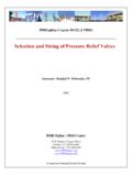
4 The Pressure /temperature limits in this Bulletin and any applicable standard or code limitation should not be exceeded. Introduction The Type HSR direct-operated, spring-loaded regulators provide In addition, the Type HSR regulators have internal relief across economical Pressure Reducing control in a variety of residential, the diaphragm to help minimize overpressure. Any outlet Pressure commercial and industrial applications. These regulators can be above the start-to-discharge point of the nonadjustable relief used with natural, manufactured or liquefied petroleum gases and valve spring moves the diaphragm off the relief valve seat, have the same inlet and outlet Pressure capabilities. allowing excess Pressure to bleed out through the screened spring case vent. Delrin is a mark owned by du Pont de Nemours and Co. 2. Type HSR. Control (main) spring Stem Relief valve spring Valve disk Orifice Pusher post E0908_08/2007.
5 Inlet Pressure Lever Outlet Pressure Atmospheric Pressure Figure 2. Type HSR Pressure Regulator Operational Schematic Table 1. Maximum Operating Inlet Pressure ORIFICE SIZE WIDE-OPEN Cg MAXIMUM OPERATING INLET Pressure TO OBTAIN GOOD REGULATING PERFORMANCE. In. mm FOR RELIEF SIZING psig bar 1/8 125 3/16 100 1/4 60 3/8 105 30 1/2 13 185 20 Table 2. Outlet Pressure Ranges Outlet Pressure range Standard SPRING WIRE DIAMETER SPRING FREE LENGTH. Spring part Spring Closing In. mbar number color In. mm In. mm Cap Color 4 to 6 10 to 15 T14398T0012 Orange Black 6 to 8 15 to 20 T14399T0012 Yellow Black 8 to 10 20 to 25 T14405T0012 Black Black 10 to 25 to 31 T14400T0012 Silver Black 104. to 20 31 to 50 T14401T0012 Gray Black 20 to 35 50 to 87 T14402T0012 Pink Black to psig to bar T14403T0012 Light Blue Red Table 3. Standard Outlet Pressures and Set Flows Outlet Pressure range Standard outlet set Pressure STANDARD SET GAS FLOW, Scfh / Nm3/h In.
6 Mbar In. mbar 4 to 6 10 to 15 5 12. 6 to 8 15 to 20 7 17. 8 to 10 20 to 25 9 22. 10 to 25 to 31 11 27 50 / to 20 31 to 50 14 35. 20 to 35 50 to 87 1 psi bar to psig to bar 2 psi bar Table 4. Flow and Sizing Coefficients Orifice size Wide-open resizing relief sizing iec sizing coefficients C1. In. mm cg cv xt fd Fl 1/8 3/16 1/4 50 35 3/8 105 1/2 13 185 3. Type HSR. Table 5. Standard Inlet Pressures for Set Flows Orifice size INLET Pressure FOR SET flows In. mm psi bar 1/8 60 3/16 50 1/4 30 3/8 15 1/2 13 10 For each orifice size, the outlet Pressure setting is made with the same inlet Pressure regardless of outlet Pressure . Example: 3/16 in. / mm orifice uses 50 psi / bar inlet for 5 in. through 2 psi / 12 mbar through bar outlet settings. Principle of Operation Capacity Information Refer to Figure 2. When downstream demand decreases, the Pressure The high efficiency flow-through design provides maximum capacity under the diaphragm increases.
7 This Pressure overcomes the Regulator for a given orifice size. Tables 6 through 14 give the HSR Series setting (which is set by a spring). Through the action of the pusher post flow capacities at selected inlet pressures and outlet Pressure assembly, lever and stem the valve disk moves closer to the orifice and settings. Flows are in scfh (at 60 F and psia) and Nm3/h reduces gas flow. If demand downstream increases, Pressure under the (at 0 C and bar) of specific gravity natural gas. To diaphragm decreases. Spring force pushes the pusher post assembly determine equivalent capacities for air, propane, butane or nitrogen, downward and the valve disk moves away from the orifice. Type HSR multiply the listed scfh capacity by the following appropriate regulators include an internal relief valve for overpressure protection. If conversion factor: air for air, propane , butane , the downstream Pressure exceeds the Regulator setting by 7 in.
8 To nitrogen For gases of other specific gravities, multiply the psig / 17 mbar to bar, depending on the main spring used, the given SCFH capacity by and divide by the square root of the relief valve opens and excess gas escapes through the vent in the upper appropriate specific gravity. If capacity is desired in Nm3/h, multiply spring case. SCFH by Installation For Critical Pressure Drops The HSR Series regulators may be installed in any position. Use this equation for critical Pressure drops (absolute outlet Pressure However, the spring case vent should be pointed downward. If equal to one-half or less than one-half the absolute inlet Pressure ). gas escaping through the Type HSR internal relief valve could Q = P1(abs)Cg( ). constitute a hazard, the spring case vent must be piped to a location where escaping gas will not be hazardous. If the vented where, gas will be piped to another location, obstruction-free tubing or piping at least equal to the vent and the end of the vent pipe must Q = gas flow rate, scfh be protected from anything that might clog it.
9 Dimensions are Cg = gas sizing coefficient shown in Figure 6. P1 = absolute inlet Pressure , psia Type HSR Flow Capacity for Pressure For Non-Critical Pressure Drops Factor Measurement For Pressure drops lower than critical (absolute outlet Pressure greater than one-half of absolute inlet Pressure ), use the following formula: Tables 6 and 7 contain the flow capacities for the Type HSR at accuracies of +/- 1% of absolute Pressure . This data can be used in applying the Regulator in Pressure Factor Measurement (also 520 3417 P. called Fixed Factor Measurement) or other applications requiring Q = CgP1 SIN DEG. GT C1 P1. better accuracy. Normally pilot operated regulators with high accuracy are required for these applications. However, as shown in where, the table, by flow testing and by limiting the droop on flow capacity, +/- 1% of absolute Pressure is obtained.
10 Q = gas flow rate, scfh G = specific gravity of the gas Overpressure Protection T = absolute temperature of gas at inlet, Rankine Cg = gas sizing coefficient The wide-open Cg for relief sizing (see Table 1) along with the P1 = absolute inlet Pressure , psia capacity information should be used in choosing appropriate C1 = flow coefficient overpressure protection devices to ensure that none of the limits in P = Pressure drop across the Regulator , psi the Specifications section are exceeded. Then, if capacity is desired in normal cubic meters per hour at 0 C. Overpressuring any portion of a Regulator or associated equipment and bar, multiply SCFH by may cause leakage, parts damage or personal injury due to bursting of Pressure -containing parts or explosion of accumulated gas. Regulator operation within ratings does not prevent the Ordering Information possibility of damage from external sources or from debris in the Carefully review each specification and complete the Ordering Guide pipeline.