Transcription of Product Customization Guide - TSE Brakes
1 Product Customization Guide TSE Brakes , Inc. Revision Date: June 7, 2018 Revision: 4 Page: 1 of 13 Product Customization Guide CONTENTS brake chamber Clamp Repositioning Mechanical Release of Spring Brakes (Caging)..4-6 Installation Determine the Correct Push Rod USA Patents: 5,285,716 / 5,758,564 5,791,232 / 5,829,339 6,129,004 / 6,131,501 Other patents pending TSE Brakes , Inc. 2310 Industrial Drive Cullman, AL 35055 Worldwide: 256-736-6275 Toll free in 1-800-722-5721 Fax: 1-800-643-3659 Internet: Product Customization Guide TSE Brakes , Inc. Revision Date: June 7, 2018 Revision: 4 Page: 2 of 13 Product Customization Guide brake chamber Clamp Repositioning Instructions 1.
2 Put the unit on a work surface. It is strongly recommended not to unclamp or re-clamp a unit that is attached to the vehicle in place for use. To ensure a leak-free unit, this procedure should be done on a shop bench or similar work area. 2. If the unit is a service chamber , proceed to step 3. If the unit is a combination brake , make sure that the chamber is caged. (See page 4 for instructions regarding caging a spring brake ). After the spring brake has been caged, proceed to step 3. 3. Place the chamber in a vertical position with the air ports in front of you. Place a vise grip pliers on the push rod to prevent sudden separation of the service base from the piggy back.
3 Be careful not to damage the threads. NOTE: Make sure the vise grip pliers are secured on the push rod. See Figure1 FIGURE 1: 4. With the vise grip pliers in place, you can loosen the clamp nuts. This can be done by hand with a wrench or pneumatic gun. Use a 9/16 socket. See Figure 2. FIGURE 2: 5. After loosening both clamp nuts, remove one clamp nut and bolt in order to remove the clamp. Now, the service side housing can be rotated. Adjust the mounting bolts position relative to the air ports. See Figure 3. Important: IMPORTANT: In order to safely unclamp the service side of a spring brake , first cage the power (main) spring. Failure to do so makes disassembly more dangerous and re-assembly very difficult, typically resulting in service side leaks.
4 Product Customization Guide TSE Brakes , Inc. Revision Date: June 7, 2018 Revision: 4 Page: 3 of 13 Product Customization Guide FIGURE 3: 6. Once the components are rotated to the desired position, re-clamp the unit. Pay special attention to the seating of the diaphragm, making sure it is centered and flush to the housing all around. Push the service side housing onto the diaphragm and put the clamps back on. Install clamp hardware, and hand tighten the nuts. Alternately tighten the nuts with a wrench so the distance between the clamp ears are equal on both sides. See Figure 4. Figure 4: 7. The last step is to remove the vice grip pliers and apply the final torque to the clamp nuts.
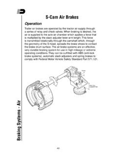
5 With a torque wrench, apply a torque of 22-31 ft-lbs (30-42 Nm). See Figure 5. FIGURE 5: NOTE: As final inspection, verify the clamp ears are equally spaced on both sides. Otherwise, it is possible for one side to have too much gap to achieve proper sealing. (Unbalanced clamp ear gaps increase the likelihood of a leak.) Product Customization Guide TSE Brakes , Inc. Revision Date: June 7, 2018 Revision: 4 Page: 4 of 13 Product Customization Guide Mechanical Release of Spring brake (Caging) Caging the Spring brake 1. Remove the dust plug from the release tool access hole in the center of the spring housing. See Figure 1. 2. Remove the release tool assembly from its holder on the adapter base (as shown) or from its holder in the spring housing (not shown).
6 See Figure 1. Figure 1: 3. Apply vehicle or shop pressure, 120 psi ( bar) or 90 psi ( bar) minimum, to the emergency side of the brake . Maintain vehicle or shop air pressure (if shop or vehicle air is not available, see page 5, Optional Method) 4. Insert the release tool bolt through the release tool access hole in the center of the spring housing and into the pressure plate that is inside the spring housing. See Figure 2. Figure 2: 5. Once fully inserted, turn the release tool bolt turn clockwise. 6. Pull the release tool bolt to ensure the bolt s cross-pin ears are properly seated on the pressure plate. 7. Assemble the release tool washer(s) and nut on the release tool bolt to finger-tight.
7 8. Release the air pressure. The brake is now caged. WARNING: Do not attempt to mechanically release (cage) the spring on any spring brake that shows sign of structural damage, significant corrosion or any other damage that the operator or mechanic deems unsafe. Handle damaged spring Brakes with extreme caution. Caging the spring or disassembling the chamber may result in a forceful release of the chamber and/or its contents, which could cause death, severe personal injury and/or personal property damage. REMOVE DUST PLUG RELEASE TOOL INSERT RELEASE BOLT RELEASE BOLT TURN CLOCKWISE RELEASE TOOL, WASHER AND NUT SPRING HOUSING Product Customization Guide TSE Brakes , Inc.
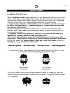
8 Revision Date: June 7, 2018 Revision: 4 Page: 5 of 13 Product Customization Guide Optional Method (Mechanical Caging) 1. Using a flashlight, look through the access hole for the pressure plate (spring plate). It should be located (64-76 mm) from the access hole. 2. Insert the release tool bolt through the access hole, all the way into the pressure plate that is inside the spring housing. See Figure 2. (previous page) 3. Turn the release tool bolt turn clockwise. Pull the release bolt and make sure the bolt s cross-pin ears sit properly on the pressure plate. 4. Assemble the release tool washer(s) and nut on the release tool bolt to finger-tight. 5.
9 To cage the main spring mechanically, tighten the release tool nut with a hand wrench (DO NOT USE AN IMPACT WRENCH) and make certain the service push rod is retracting while tightening. See Figure 3. Figure 3: 6. When the service push rod stops moving and/or the torque reaches 35 ft-lbs (47 Nm), or the release tool extends beyond the nut more than ( mm), stop torqueing the release tool bolt assembly. The brake is considered caged. Release Tool Bolt Torque: 35 ft-lbs (47 Nm) Maximum Warning: Over-torqueing the Release Tool Nut can cause pressure plate, washer and/or spring housing damage, resulting in sudden release of the main spring and potentially causing the release tool, washer, nut and/or fragments to become airborne which could cause death, severe personal injury and/or personal property damage.
10 IMPORTANT: These instructions apply only when the spring brake is not pressurized. RELEASE TOOL WASHER AND NUT RELEASE BOLT TURN CLOCKWISE WARNING: Do not over-torque the release tool bolt assembly. Over-torqueing the release tool bolt nut can cause pressure plate damage. Product Customization Guide TSE Brakes , Inc. Revision Date: June 7, 2018 Revision: 4 Page: 6 of 13 Product Customization Guide Inspection of the Alignment of the Pressure Plate Visual Inspection: This inspection procedure helps to ensure the pressure plate can be caged manually (without air) with the universal release bolt. By removing the dust plug and using a flashlight, look through the spring housing access hole to determine if the pressure plate tool access hole is able to accept the release bolt.