Transcription of Product Data - Carrier
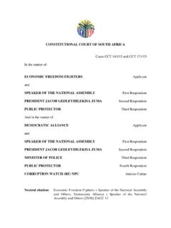
1 Product Data25 HHA4 Performancet Series Heat Pumpwith Puronr Refrigerant1-1/2 to 5 Nominal TonsCarrier Heat Pumps with Puronr refrigerant provide a collectionof features unmatched by any other family of equipment. The25 HHA4 has been designed utilizing Carrier s Puron environmentally sound refrigerant allows you to make aresponsible decision in the protection of the earth s ozone : Ratings contained in this document are subject tochange at any time. Always refer to the AHRI directory( ) for the most up to date LEADING FEATURES / BENEFITSE nergy EfficiencyS14 15 HSPF (Based on tested combinations)SoundSLevels as low as 69 dBADesign FeaturesSSmall footprintSWeatherArmort cabinet All steel cabinet construction Mesh coil guardReliability, Quality and ToughnessSScroll compressorSFactory supplied filter drierSHigh pressure switchSLow pressure switchSAccumulatorSLine lengths up to 250 ( m)SLow ambient operation (down to 20_F/ withlow ambient accessories)TABLE OF CONTENTSPAGEMODEL NUMBER LINE SIZING AND COOLING CAPACITY USAGE DATA WEIGHTED SOUND POWER (dBA) WEIGHTED SOUND POWER (dBA)
2 WITH ACCESSORYSOUND SHEILD SUB POINT AHRI COMBINATION COOLING PUMP HEATING PERFORMANCE ONLY RATINGS SPECIFICATIONS NUMBER NOMENCLATURE12345678910111213 NNAAA/NNNNA/NA/NA/NNN25 HHA418A0030 ProductSeriesProductFamilyProductTypeMaj orSeriesSEERC oolingCapacityVariationsOpenOpenVoltageM inorSeries25 = HPH = HPH = HorizontalDischarge4 = 14 SEERA =Standard0 = Not Defined0 = Not Defined3 = 208/230-15 = 208/230-36 = 460/30, 1, of the AHRI CertifiedTM Mark indicates amanufacturer s participation in the program For verification of certification for individual products, go to PHYSICAL DATAUNIT SIZE - SERIES18-3024-3030-3036-30, 50, 6048-30, 50, 6060-30, 50, 60 COMPRESSOR TYPES crollREFRIGERANTP uron (R-410A) ControlTXV (Puron Hard Shutoff) Charge lb (kg) ( ) ( ) ( ) ( ) ( ) ( )COND FANP ropeller Type, Direct Drive Air DischargeHorizontal Air Qty (CFM)128512852615261527852785 Motor HP1/121/121/41/41/41/4 Motor RPM800800800800800800 COND COIL Face Area (Sq ft) Fins per Rows222222 Circuits336566 VALVE CONNECT.
3 (In. ID) Vapor5/83/43/47/87/87/8 Liquid3/8 REFRIGERANT TUBES* (In. OD) Rated Vapor*5/83/43/47/87/81 1/8 Max Liquid Line{3/8* Units are rated with 25 ft ( m) of lineset length. See Vapor Line Sizing and Cooling Capacity Loss table when using other sizes and lengths of : See unit Installation Instruction for proper installation.{ See Liquid Line Sizing For Cooling Only Systems with Puron Refrigerant LINE SIZING AND COOLING CAPACITY LOSSLONG LINE APPLICATION: An application is considered Long line when the total equivalent tubing length exceeds 80ft. ( m) or when there is more than 20 ft. ( m) verticalseparation between indoor and outdoor units. These applicationsrequire additional accessories and system modifications forreliable system operation.}}
4 The maximum allowable totalequivalent length is up to 250 ft. ( m).The maximum vertical separation is 200 ft. ( m) whenoutdoor unit is above indoor unit, and up to 80 ft. ( m)when the outdoor unit is below the indoor unit. Refer toAccessory Usage Guideline below for required accessories. SeeLongline Application Guideline for required piping and systemmodifications. Also, refer to the table below for the vapor tubediameters based on the total length to minimize the coolingcapacity Nominal Size(Btuh)MaximumLiquid LineDiameters(In.) ODVapor LineDiameters(In.) ODCooling Capacity Loss (%)Total Equivalent Line Length ft. (m)StandardApplicationLong Line Application Requires Accessories26-50( )51-80( )81-100( )101-125( )126-150( )151-175( )176-200( )201-225( )226-250( )18,0001-Stage Puron HP3/81/212346789105/800111223324,0001-St age Puron HP5/80112334453/400001111130,0001-Stage Puron HP5/81233456783/40011122237/800001111136 ,0001-Stage Puron HP5/8124567910113/40011223347/8000011112 48,0001-Stage Puron HP3/40123455677/800112223360,0001-Stage Puron HP3/4124567910117/80122344551-1/80001111 11 Applications in this area are long line.
5 Accessories are required as shown recommended on Long Line Application GuidelinesApplications in this area may have height restrictions that limit allowable total equivalent length, when outdoor unit is below indoor unit See Long Line Applica tion Guidelines4 ACCESSORIESKIT NUMBERKIT NAMEUnit Size (Voltage/Series)018(30)024(30)030(30)036 (30)036(50)036(60)048(30)048(50)048(60)0 60(30)060(50)060(60)KAACH1701 AAAC rankcase HeaterXXSSSS KAACH1601 AAAC rankcase Heater XX XX KAACH1901 AAAC rankcase Heater X XKAACS0201 PTCPTC Start AssistXXXX X X KAAFT0101 AAAE vaporator Freeze StatXXXXXXXXXXXXKAATD0101 TDRTime Delay RelayXXXXXXXXXXXXKHAIR0201 AAAI solation RelayXXXXXXXXXXXXKSALA0301410 Low Ambient KitXXXXXXXXXXXXKSALA0801 AAAM otorMasterr 230vXXXXXXXXXKSALA0901 AAAM otorMasterr 460vXXX53DS-900---070 Wind BaffleX 53DS-900---087 Wind Baffle X 53DS-900---071 Wind Baffle XXXX 53DS-900---088 Wind Baffle XXXXXX53DS-900---077 Wall Mounting KitXX 53DS-900---078 Wall Mounting Kit XXXXXXXXXXKSASH2301 COPS ound Blanket KitXXXX KSASH2401 COPS ound Blanket Kit XXXXXXKHALS0401
6 LLSS olenoid Valve KitXXXXXXXXXXXXKSAHS1501 AAAC apacitor Relay Start AssistXXXX X X KSACY0101 AAAC ycle ProtectorXXXXXXXXXXXXX = AccessoryACCESSORY THERMOSTATSPART NUMBERDESCRIPTIONTP WEM01C r ThermostatTP PRH01 Aedge Programmable Relative Humidity ThermostatTP PHP01edge Programmable ThermostatTP NRH01edge Non Programmable Relative Humidity ThermostatTP NHP01edge Non Programmable ThermostatTC WHS01Wi Fi ThermostatTC PHP01 Programmable ThermostatTC NHP01 Non Programmable ThermostatTCSNHP01 Non Programmable Standard Screen ThermostatTHERMOSTAT ACCESSORIESPART NUMBERDESCRIPTIONTHERMOSTATS USED WITHTP EXPedge EXP CardProgrammable edge thermostatsTSTATCCSEN01 BOutdoor Air Temperature SensorTP Pxx, TP NxxTSTATXXCNV10 Thermostat Conversion Kit (4 to 5 wire) 10 packAll Carrier branded thermostatsTX MBP01 Medium Decorative BackplateTC NxxTX LBP01 Large Decorative BackplateTP Pxx, TP Nxx, TC Pxx5 ACCESSORY USAGE GUIDELINEA ccessoryREQUIRED FOR LOW-AMBIENTCOOLING APPLICATIONS(Below 555F / )REQUIRED FORLONG LINE APPLICATIONS*(Over 80 ft.)
7 / m)REQUIRED FORSEA COAST APPLICATIONS(Within 2 miles / km)Ball Bearing Fan MotorStandardStandardStandardCompressor Start Assist Capacitor andRelayYe sYe sNoCrankcase HeaterYe sYe sNoEvaporator Freeze ThermostatYe sNoNoIsolation RelayYe sNoNoLiquid Line Solenoid ValveNoSee Long-Line ApplicationGuidelineNoMotorMaster ControllerYe sNoNo* For tubing line sets between 80 and 200 ft. ( and m) and/or 20 ft. ( m) vertical differential, refer to Residential Split-System LonglineApplication Description and Usage (Listed Alphabetically)1. Ball Bearing Fan MotorA fan motor with ball bearings which permits speed reductionwhile maintaining bearing Guideline:Required on all units when using MotorMasterr2. Compressor Start Assist Capacitor and RelayStart capacitor and relay gives a hard boost to compressormotor at each start Guideline:Required for reciprocating compressors in the following applications:Long lineLow ambient coolingHard shut off expansion valve on indoor coilLiquid line solenoid on indoor coilRequired for single phase scroll compressors in the following applications:Long lineLow ambient coolingSuggested for all compressors in areas with a history oflow voltage Crankcase HeaterAn electric resistance heater which mounts to the base of thecompressor to keep the lubricant warm during off compressor lubrication on restart and minimizes thechance of liquid Guideline.
8 Required in low ambient cooling in long line in all commercial Evaporator Freeze ThermostatAn SPST temperature actuated switch that stops unit operationwhen evaporator reaches freeze up Guideline:Required when low ambient kit has been Isolation RelayAn SPDT relay that switches the low ambient controller out tothe outdoor fan motor circuit when the heat pump switches toheating Guideline:Required on all heat pumps where low ambient kit hasbeen Liquid Line Solenoid Valve (LLS)An electrically operated shutoff valve which stops and startsrefrigerant liquid flow in response to compressor operation. It isto be installed at the outdoor unit to control refrigerant off cyclemigration in the heating Guideline:An LLS is required in all long line heat pump applications to control refrigerant off cycle migration inthe heating mode.
9 See Long Line Low Pressure Switch KitFactory installed added compressor protection against loss ofrefrigerant. It cuts out the system at 50 PSI and allows operationagain at 95 PSI. Used for commercial or harsh environmentapplications for extra MotorMaster Low Ambient ControllerA fan speed control device activated by a temperature sensor,designed to control condenser fan motor speed in response to thesaturated condensing temperatures down to 20_F ( ), itmaintains condensing temperature at 100_F +/ 10_F ( + 6_C).Usage Guideline:A MotorMaster Low Ambient Controller must be usedwhen cooling operation is used at outdoor temperatures below55_F ( ).Suggested for all commercial Time Delay RelayAn optional accessory for systems that do not have an integralblower time DATAUNIT SIZE -voltage,seriesV/PHOPER VOLTS*COMPRFANMCAMAX FUSE** orCKT BRK AMPSMAXMINLRARLAFLA18-30208/230 :FLA- Full Load AmpsHACR- Heating, Air Conditioning, RefrigerationLRA - Locked Rotor AmpsNEC- National Electrical CodeRLA- Rated Load Amps (compressor)*Permissible limits of the voltage range at which the unit will operate satisfactorily** Time-Delay with 2007 requirements of ASHRAE Standards WEIGHTED SOUND POWER (dBA)Unit SizeStandardRating(dBA)Typical Octave Band Spectrum (dBA, without tone adjustment) : Tested in accordance with AHRI Standard 270-08 (not listed in AHRI).
10 A WEIGHTED SOUND POWER (dBA) WITH ACCESSORY SOUND SHEILDUnit SizeStandardRating(dBA)Typical Octave Band Spectrum (dBA, without tone adjustment)125250500100020004000800018N/ A-------24 :Tested in accordance with AHRI Standard 270-08 (not listed in AHRI).Accessory sound shield will not accommodate unit sizes 18 and SUB COOLING (TXV TYPE EXPANSION DEVICE)UNIT SIZE-SERIESREQUIRED SUBCOOLING F ( C)1812 ( )2414 ( ))3011 ( )3614 ( )4811 ( )6012 ( )7 DIMENSIONS ENGLISH8 DIMENSIONS SI9 BALANCE POINT (B,F)061L25 HHA448 AFB4 CNP048L25 HHA436 AFFMANP037 BUILDING HEAT LOSS, UNIT INTEGRATED HEATING CAPACITY, MBTUHkWOUTDOOR TEMPERATURE, F ( C)-10 ( )0 ( )10 ( )20 ( )30 ( )40 ( )50 ( )60 ( )70 ( )80 ( )BASED ON INDOOR ENTERING AIRAT 70 F ( C) AND AT RATED CFM 10 TESTED AHRI COMBINATION RATINGS*NOTE.