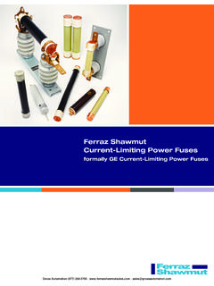
Transcription of Product Selection Guide - sps-sales.com
1 Product Selection GuideTABLE OF CONTENTST1 Series: 40, 50 & 60 - Series: 60, 100 - Series: 100 & 225 - Series: 250, 400 & 800 - Selection Guide | & SPECSI ntroductionUniversal Electric Corporation (UEC) is the leader in electrical power distribution in the mission critical, commercial and light industrial industries with STARLINE Track Busway. This system was designed to meet the rugged specification of the UL857, Busway and Associated Fittings, with the flexible features of track lighting - and is available in systems with 40, 50 & 60 amps with isolated ground. It is the simple, versatile, fast and economical solution for supplying power to electrical loads and is unique because the busway can be instantly tapped at any location, with a variety of plug-in units.
2 The Product Selection Guide was developed to help the design engineer understand and consider all of the options available with STARLINE Track Busway when designing a system. This Guide is all-inclusive; however, UEC excels at collaborating with design engineers to provide solutions for any application. If you have a need that is not found in this Guide , please contact us at 1-800-245-6378 or email us at We will be happy to answer your questions over the telephone or schedule a visit with one of our local , if viewing this Guide in print, please keep in mind that this is a working document. UEC reseves the right to change information and descriptions of listed services and products. The latest version of this Guide is available for download at SpecsThis specification covers the electrical characteristics and general requirements for a track busway system, hereafter referred to as (Track Busway).
3 The system shall be designed primarily for overhead distribution of electrical power. Supporting designated work areas and equipment. Once installed the Busway will provide a simple, versatile, fast and economic means of distributing power. Loads fed from a variety of plug-in units can be easily added or removed without shutting power down to the Track Busway shall be designed and manufactured to the following standards:1. Underwriters Laboratories Standard, UL 857 The common UL, CSA, and ANCE Standard for Busways that is derived from the fifth edition of CSA Standard No. 27, the twelfth edition of UL 857, and the second edition of Low Voltage Switchgear and Controlgear Assemblies, Part 1: Type Tested and partially type tested Assemblies, IEC 61439-1 & IEC 61439-6.
4 *All standards and certifications available upon requestT1 | SeriesTABLE OF CONTENTSINTRODUCTION & OF LAYOUT SYSTEM LAYOUT RELATIONSHIP , 50T1 & 60T1 SystemsSTRAIGHT SECTIONS: STRAIGHT SECTIONS: Product ELBOW SECTIONS: Product TEE SECTIONS (cont'd).. TEE SECTIONS: Product CROSS SECTIONS: Product FEED END FEED UNITS: Product FEED ABOVE FEED UNITS: Product FEED CONNECTOR END FEED CONNECTOR UNITS: Product FEED PENDANT FEED UNITS: Product : SUPPORT : SUPPORT : SUPPORT : CONNECTION | LAYOUT DRAWINGEnd Feed UnitStraight SectionEnd CapTe eElbowSupport HardwareT1 Units:For further information on applicable T1 plug-in unit options, please visit the Plug-In Units sectionIn-Line ConnectorHousing CouplerPOLARITY TIPS | SeriesSTARLINE utilizes a unique polarizing method to prevent mismatched components from being inadvertently connected to each other.
5 The system is designed to prevent cross phasing during installation. It is particularly important to understand this design concept prior to ordering and/or installing some components. For example, if the face direction of a STARLINE plug-in unit is important in your installation consider that they will always face the side with the polarizing Units face this direction; the side with the polarizing stripeEnd CapEnd CapPlug-In Unit Front-Facing Direction =Internal-Right Tee (IR)External-LeftTee (EL)Polarizing stripeEnd CapInternal Elbow ConnectorExternal Elbow ConnectorPolarizing Stripe =End FeedSYSTEM LAYOUT TIPS | SeriesPower FeedsDetermine location of power feeds based on relation to power source, existing feeders and voltage drop concerns for longer runs.
6 Support HardwareSupport hardware is spaced no more than 10 ft apart. Refer to page for support hardware details. Contact your local Starline applications engineer for any questions. InstallationPrinted installation drawings are supplied with each system shipment and they are also available for download online at CAD files of these drawings are also available by contacting your local Starline applications Housing SectionsStandard Busway lengths are available in 20, 10 and 5-foot increments. Although the factory can cut individual STARLINE Track Busway sections to any length under 20 feet, it is highly recommended to keep all layout runs in increments of 5 feet to simplify layout and installation. Custom lengths can be made but can increase lead time and make layout and installation a bit more complex.
7 Busway Tees and Elbows SectionsTry to keep all runs as straight as possible as tees and elbows are added cost. With grid or any other bi-directional applications, there is a choice of two-plane with each direction on a separate plane or using cross sections if single-plane is required. Single-plane applications can provide power in both directions as well as parallel runs. Length of Busway for a One Volt Drop in Line to Line Voltage:SYSTEM DESIGNATIONDISTRIBUTED LOADVOLTAGE DROP @ PF Single PhaseVOLTAGE DROP @ PF Three Phase40T140 amps36 amps29 amps29 RELATIONSHIP TIPS | SeriesWhen ordering material, it is important to understand the relationship between various components. Examples: Each straight section requires a connector and coupler.
8 Three Housing Couplers (HC) are needed for each Tee Connector. General support hardware rule to follow: 10 ft maximum spacing between supports and we recommend 10% more than the required quantity to cover potential layout changes. Total Power Feeds and End Caps can be determined by counting the total number of unconnected runs. Before specifying or ordering elbow or tee connectors, it is important to understand polarity and the relationship to direction of outlets. Please refer to pg. Polarity Tips for more , 50T1, 60T1 SystemsSTRAIGHT SECTIONS Product DescriptionTrack Busway straight sections consist of an extruded aluminum shell with insulated copper conductor strips mounted on the top interior wall.
9 The aluminum housing acts as a 100% ground path and each straight section has an open access slot over its entire length for the insertion of snap-in plug-in units. Housing configurations include 2 and 4 pole varieties, 480/277 Volts max. Track Busway straights are connected together using a joint kit, which includes an in-line connector and housing coupler (found under Accessories).Sections are supported every 10 ft max. and can support 75 lbs hanging weight between vertical supports. Four-pole Busway is normally used in 3-phase/4-wire power systems. Four-pole Busway may be used for 2 independent single-phase circuits at different voltages. Sections can be factory cut to any | Housing Coupler: placed over top of connector to make a mechanical connectionConnector: placed in between two pieces of busway to make an electrical connectionTwo PoleFour Pole(N)(L1)(L2)(L3)L1 = BlackL2 = RedL3 = BlueN = white or (N)(L1)WEIGHT: 10 ft.
10 40 Amp, 2 or 4 pole: 7/8 lbs10 ft. 50 Amp, 2 or 4 pole: 7/8 lbs10 ft. 60 Amp, 2 or 4 pole: 8/9 lbs40T1, 50T1, 60T1 SystemsSTRAIGHT SECTIONS: RECESSED Product DescriptionT1 housing is also available in a slightly different design, specifically tailored for Busway that is meant to be installed recessed into a suspended ceiling. Busway straight sections are available in 20, 10, and 5 ft. lengths for two standard drop or suspended ceiling configurations. | Wall InstallationStandard and Regular Tile InstallationFor recessed housing, please choose 'R1' as opposed to 'T1' in your Product number.*refer to pg. option 4. Compatibility (frame compatibility)4. Compatibility (frame compatibility)T1 T1 systemsR1 T1 systems (Recessed housing) 40T1, 50T1, 60T1 SystemsSTRAIGHT SECTIONS: Product | S 040 T1 C 4 S - 0200 C - STD0 10.