Transcription of Profibus-DP - Control Techniques
1 User Guide Profibus-DP Option Module For Unidrive Part Number: 0460-0075 Issue Number: 3 SAFETY INFORMATION Persons supervising and performing the electrical installation or maintenance of a Drive and/or an external Option Unit must be suitably qualified and competent in these duties. They should be given the opportunity to study and if necessary to discuss this User Guide before work is started. The voltages present in the Drive and external Option Units are capable of inflicting a severe electric shock and may be lethal. The Stop function of the Drive does not remove dangerous voltages from the terminals of the Drive and external Option Unit.
2 Mains supplies should be removed before any servicing work is performed. The installation instructions should be adhered to. Any questions or doubt should be referred to the supplier of the equipment. It is the responsibility of the owner or user to ensure that the installation of the Drive and external Option Unit, and the way in which they are operated and maintained complies with the requirements of the Health and Safety at W ork Act in the United Kingdom and applicable legislation and regulations and codes of practice in the UK or elsewhere. The Drive software may incorporate an optional Auto-start facility.
3 In order to prevent the risk of injury to personnel working on or near the motor or its driven equipment and to prevent potential damage to equipment, users and operators, all necessary precautions must be taken if operating the Drive in this mode. The Stop and Start inputs of the Drive should not be relied upon to ensure safety of personnel. If a safety hazard could exist from unexpected starting of the Drive, an interlock should be installed to prevent the motor being inadvertently started. GENERAL INFORMATION The manufacturer accepts no liability for any consequences resulting from inappropriate, negligent or incorrect installation or adjustment of the optional operating parameters of the equipment or from mismatching the Drive with the motor.
4 The contents of this User Guide are believed to be correct at the time of printing. In the interests of a commitment to a policy of continuous development and improvement, the manufacturer reserves the right to change the specification of the product or its performance, or the contents of the User Guide, without notice. All rights reserved. No part of this User Guide may be reproduced or transmitted in any form or by any means, electrical or mechanical including photocopying, recording or by any information storage or retrieval system, without permission in writing from the publisher. Copyright January 2001 Control Techniques SSPD Author Paul Bennett Issue Code Issue 3 System File Hardware (UD73) Issue 1 Firmware (UD73)
5 Contents 1 Introduction 4 Profibus-DP Interface for Unidrive 4 Product Conformance Certification 4 Overview Specification 4 2 Mechanical Installation 4 Unidrive 4 3 Electrical Installation 4 Profibus-DP Connectors 4 Profibus-DP Data Connections 4 ERNI Connector 4 Siemens Connector 4 Profibus-DP Cable 4 Profibus-DP Cable Screen Connections 4 Profibus-DP Network Termination 4 ERNI Termination Connector 4 Siemens Connector 4 Maximum Network Length 4 4 Getting Started 4 Basic Communications Quick Start 4 Profibus-DP Node Address 4 Profibus-DP Data Rate 4 Data Format 4 Network Status 4 Network Loss Trip 4 Initialising Set-up Changes 4 5 Cyclic Data 4 What is Cyclic Data?
6 4 What is Data Consistency 4 Profibus-DP Data Formats 4 Mapping Parameters on Unidrive 4 Internal 32-Bit Parameters on UD70 4 Storing Parameters 4 Saving Unidrive Parameters (Menu 1 to 19) 4 Saving UD70 Parameters (Menu 20 and Internal) 4 Mapping Conflicts 4 Control Word Mapping Conflicts 4 Fieldbus Control Word for Unidrive 4 Fieldbus Status Word for Unidrive 4 Disabling Cyclic Data Channels 4 6 Non Cyclic Data 4 CT Single Word Format 4 Reading parameters using Mode 1 4 Writing parameters using Mode 1 4 Profibus-DP Set-up using Non-Cyclic Data 4 7 GSD Files 4 What are GSD Files? 4 Unidrive GSD File 4 Data Consistency 4 Profibus-DP Data Formats 4 8 Diagnostics 4 Fieldbus Code 4 Firmware Version 4 System File Version 4 Node Address 4 Network Data Rate 4 Network Status 4 No Data Transfer 4 Unidrive Trip Codes 4 9 Advanced Features 4 Network Loss Trip 4 Unidrive Sequencing Mode 3 4 Drive Reset Using The Profibus-DP Network 4 Reset W ithout DPL Code 4 Reset Using CT Mode Non-Cyclic Communications 4 Reset Using DPL Code 4 Non-Cyclic Parameter Store 4 Endian Format 4 EVENT Task Trigger on UD70 4 Multi-Master Networks 4 10
7 Quick Reference 4 Complete Parameter Reference 4 Profibus-DP Data Formats 4 Fieldbus Control Word 4 Fieldbus Status Word 4 Unidrive Trip Codes 4 Issue Number: 3 5 1 Introduction NOTE Unidrive parameters are denoted in this manual by # , where MM refers to the menu number, and PP refers to the parameter number within that menu. Please refer to the Unidrive Advanced User Guide for a full list of parameter defi nitions. Profibus-DP Interface for Unidrive The Unidrive Profibus-DP interface is supplied as an option module, with the Profibus-DP using a UD70 as the host.
8 The UD70 does not lose any functionality when the Profibus-DP interface is fitted. The fastest data rate currently supported is Mbits/sec. The Unidrive supplies all power requirements for the Unidrive Profibus-DP interface. There is no provision for a back-up +24V power supply. Product Conformance Certification The Unidrive Profibus-DP interface (with firmware, system file and GSD file) was submitted to the profibus Nutzerorganisation for conformance testing. All tests were successful, and the profibus Nutzerorganisation awarded full profibus Conformance Certification.
9 ( profibus Certificate No. Z00600) NOTE Unidrive Profibus-DP interfaces fitted with firmware or earlier do NOT have Product Conformance Certification. Overview Specification Auto slave configuration of data format and data consistency during Profibus-DP network initialisation. Supported data rates (bits/sec): , 500k, , , , Three 16 bit input/output words, all can be mapped to or from Unidrive parameters CT Single W ord Format non-cyclic data channel 6 Issue Number.
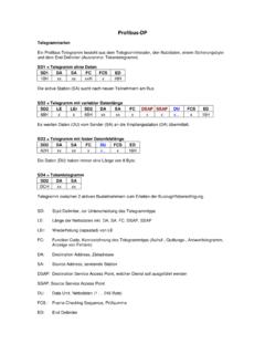
10 3 2 Mechanical Installation Warning The Unidrive must be disconnected from the mains supply before installing or removing an option module. Unidrive 1. Slide the option module into the Unidrive. 2. Push the option module into the Unidrive until it clicks into place.