Transcription of Programmable Logic controller (PLC) in computer …
1 55 Programmable Logic controller (PLC) in computer Numerical control (CNC) machine Prof. Tamboli J. , Mr. Shinde Shailesh 1M. E. (Electronics), Rajarambapu Institute Of Technology, Islampur, Sangli, Maharashtra, India, 2M. Tech. (Electronics Technology-Appear), Shivaji University, Kolhapur, Maharashtra, India, Abstract:-Now a days, industrial requirement has for the reliability of the control equipment, electromagnetic interference, power voltage fluctuation, mechanical vibration, reliable work and strong anti-jamming ability. PLC has designed for applications in industrial environments designed electronic digital computing system operations and take a multilevel hardware and software anti-jamming measures in the design and manufacturing is widely used in CNC machines and other industrial control ,including continuous control of each axis position, control of spindle rotation on/off, tool changer, clamping and loosening, cooling, chip and other auxiliary Logic control, make the CNC machine tool structure is more compact, greatly improve the response speed and reliability.
2 Keywords:- Programmable Logic control (PLC), computer numerical control (CNC), Ladder Diagram, motor control circuits, interlock circuits. I. INTRODUCTION In PLC ( Programmable Logic controller ) combines computer technology, automatic control technology and communication techniques is made for industrial control computer system. For requirements of the PLC sequence control saving some digital operation function of the microcomputer and strengthen the Logic control function. To realize the automatic control device of PLC between the relay control and computer control but also overcomes some disadvantages of microcomputer can be used in harsh industrial environments has strong anti-interference ability.
3 In addition input/output part adopts controllers, memory also set a wide variety of protection and shielding PLC uses software to realize the user control Logic , compact structure, small volume easy to load the machine internal or electrical box, easy to mechanical and electrical integration of action to achieve complex control Logic and CNC machine. Now a days most of PLC adopts and relay Logic control circuit diagram is similar to the ladder diagram of program design , working principle of graphic symbol image intuitive and easy to understand hamming is simple, convenient operation, flexible change can also be connected to programmer, personal computer etc. and easily implement program of display, edit, diagnosis, storage and delivery etc.
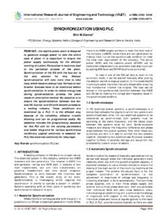
4 Its working principle is shown in fig 1. International Journal of Recent Trends in Engineering & Research (IJRTER) Volume 04, Issue 02; February - 2018 [ISSN: 2455-1457] @IJRTER-2018, All Rights Reserved 56 Fig 1:- PLC basic composition and working principle. II) PLC is mostly used in CNC machine tool :- 1) Built in type :- Built in type PLC belongs to the CNC device, signal between PLC and CNC device to transmit on CNC device between PLC and CNC machine tool through the CNC I/P and O/P interface circuit for signal transmission. 2) Independent Type: - Independent PLC is also called external or general PLC. On the NC machine tool, the independent type PLC is independent of the CNC device, with the hardware structure and software functions can complete the control independent.
5 III) CNC machine tool, The PLC can realize the function:-CNC machine tools in the design of PLC system and the design of the CNC system is inseparable, the machine numerical control system is generally take or provide the function of PLC. 1) CNC machine tools using a variety of switch quantity control, the movement of the machine tool, including the control switch ,trip switch ,close to switch ,pressure switch ,temperature switch etc, through all kinds of switch signal to the PLC and after PLC Logic operations to control signal output to the object. 2) PLC output signal via the relay, contractor, hydraulic or pneumatic solenoid valve, control knife library manipulator and rotary center workbench etc. 3) PLC collects all kinds of fault signal, the warning signs in the appropriate position issued by the CNC system alarm or alarm text signal.
6 4) PLC is to achieve CNC machine tools (MT) of switch control through the communication between the CNC system (CNC) and machine tool (MT), namely the exchange of information between PLC and CNC, PLC and MT. IV) Information interchange for CNC machine tools:-Information interchange for CNC machine tool as shown in fig 2 and mainly consists ofthe following four parts. 1) MT->PLC :-Mainly a variety of switches, buttons and other information on the machine operator panel, including the machine start and stop, work mode, rate, spindle positive inversion and stop cutting fluid ,the opening and closing, chuck and loosen, each coordinate point control, ATC instructions, the over travel limit, spindle servo protection monitoring signal, feed system for signal switch signal.
7 Switch signal machine side can be entered into the PLC by switch of PLC input interface, the X signal in Fig 2, except for a handful of signal, the meaning of the vast majority of the signal and the PLC occupied address can be defined by the PLC program design. International Journal of Recent Trends in Engineering & Research (IJRTER) Volume 04, Issue 02; February - 2018 [ISSN: 2455-1457] @IJRTER-2018, All Rights Reserved 57 F-- Y-- G-- X-- Fig:-2 Information transmission between CNC, PLC and MT 2) PLC MT :- PLC to machine signal control machine actuator, such as solenoid valve, contractor and ensure the machine all the moving parts of the signal and fault indicator etc.
8 Signal PLC to control the machine are delivered through a PLC switch output interface to MT, the y signal in fig2 ,all switch output signals and the meaning of the PLC address are occupied address can be defined by the PLC program design. 3) CNC PLC :- Mainly refers to the function code M,S,T,F etc., S-function by converting the output spindle speed control instructions in PLC, T-function is managed through the PLC tool storage, for automatic tool exchange, M-function depending on the m code control spindle, the gearshift of spindle gear box speed, opening and closing of cutting fluids, chuck clamping, loosen the tool change manipulator and matching center tool and other actions. F-function to complete the output axis feed rate is controlled by PLC servo to the PLC information is available (for CNC side) done through the switch output signal, can also be delivered directly to the PLC registers, the F signal in fig 2, All of the CNC to the PLC signal meaning and address (switching and register address) have been determined by CNC manufactures, PLC programmers can use, but cannot be changed or deleted.
9 4) PLC CNC:- Information of PLC to CNC mainly M,S,T,F functional response signals and the axis of reference signals, moving parts of machine tools and fault information PLC to CNC information completed by the switching input signals, the G signal in Fig 2, All of the PLC to CNC signal meaning and address (switching and register address) have been determined by CNC manufactures, PLC programmers can use ,but cannot be changed or deleted. Different ways of information exchange between CNC and PLC functions are very different, but its most basic function is the CNC will be required for the implementation of the M, S, T, F function code sent to PLC, then PLC control to complete the corresponding action, PLC signal flow diagram for CNC machine tool in fig 3.
10 CNC Signal PLC Signal Machine (MT) Signal International Journal of Recent Trends in Engineering & Research (IJRTER) Volume 04, Issue 02; February - 2018 [ISSN: 2455-1457] @IJRTER-2018, All Rights Reserved 58 Fig 3:- PLC signal flow diagrams 5) Ladder diagram setting failure detection: - In PLC control system most of faults not due to PLC but it is due to the external components fault, because the PLC has high reliability. Once the system detects a component failure, not only with sound and light alarm function and can immediately display fault code, so that users can quickly determine the cause of program not only can detect each fault and displays also judged most critical initial faults automatically.