Transcription of PROJECT PROPOSAL E XAMPLES PROJECT PROPOSAL …
1 Updated September 14, 2007 !Hardware PROJECT Example !!!1 PROJECT PROPOSAL - EXAMPLES The following examples are drawn from past student reports, and illustrate how the general guidelines can be applied to a variety of design projects. They should help you get a sense of what is expected for the final PROJECT PROPOSAL document. The technical details have been removed in order to highlight the report structure and organization as opposed to the technical content or writing style. These examples have not been properly formatted with the appropriate use of tables, bullets, references, etc. Example #1: Controller for Frequency Modulated Spectroscopy Executive Summary Updated September 14, 2007 !Software PROJECT Example !!!1 PROJECT PROPOSAL - EXAMPLES The following examples are drawn from past student reports, and illustrate how the general guidelines can be applied to a variety of design projects. They should help you get a sense of what is expected for the final PROJECT PROPOSAL document.
2 The technical details have been removed in order to highlight the report structure and organization as opposed to the technical content or writing style. These examples have not been properly formatted with the appropriate use of tables, bullets, references, etc. Example #2: Secure watermark-based multimedia authentication system Executive Summary !"#$%&'#()*#+'$,(#$-.$'&/&0+1$2#'&+$"+($ 1#'$0-$+3$&34*#+(#'$'#2+3'$.-*$'&/&0+1$4 -30#30$)*-0#40&-3$2#4"+3&(2(5$$!"&($)*-6 #40$&37#(0&/+0#($0"#$,(#$-.$%+0#*2+*8&3/ $+($+$2#+3($0-$)*-0#40$'&/&0+1$4-30#309$ +3'$)*-)-(#($+$(#4,*#$%+0#*2+*8:;+(#'$2, 10&2#'&+$+,0"#30&4+0&-3$(<(0#2$0"+0$%&11 $+11-%$+$,(#*$0-$#2;#'$+3'$+,0"#30&4+0#$ &2)#*4#)0&;1#9$ #''&3/$2#0"-'9$%"&4"$&($2-*#$.1#E&;1#$0" +3$+$(0*&401<$.*+/ ,(0$2#0"-'5$$!"#$%&'()&*#+,&&)-.,/01/2#0 )-+&1.'1,/#,$#'()#0)-12/#,$#'()#3)&1$1+" '1,/#-').4$$!-$7+1&'+0#$-,*$(<(0#29$%#$% &11$,(#$&2+/#($.*-2$+$(+2)1#$1&;*+*<$0"+ 0$+*#$#2;#''#'$%&0"$+$%+0#*2+*85$D+*&-,( $F+00+48(G$% #$2+'#$0-$4-)&#($.)))))))))))))))
3 $0"#$%+0#*2+*8#'$&2+/#(5$H#$%&11$2#+(,*# $0"#$.+1(#$)-(&0&7#$+3'$3#/+0&7#$*+0#($% "&4"$+*#$'#.&3#'$+($555$$!-$7#*&.<$-,*$&2)#*4#)0&;&1&0<$*#I,&*#2#309$%#$%&11$2#+(,*#555$$!"#$(<(0#2$% #$4-'#'$,( 9$(&34#$0"#$)*-0-0<)#$( +*#$&37-8#($)*#:'#.&3#'$J+01+;$K2+/#$L*-4#((&3/$.,340&-3(5$M$%#+83#(($-.$0"&($'#(&/3$&($0"#$.+40$0"+0$&0$2+<$3-0$;#$#+( 1#9$(&34#$+$.,11$7#*(&-3$-.$J+01+;$%&0"$0"#$K2+/#$L*-4#(( -E$&3(0+11#'$&($3#4#((+*<$0-$*,3$0"#$)*-/*+25$$N3#$-.$0"#$2+&3$)*-6#40$*&(8($&($0"+0$ #$ 1#$0-$*,3$+11$0"#$3#4#((+*<$0#(0($0-$4-30*-1$0"#$;#"+7&-*$+3'$+44,*+4<$-.$0"#$(<(0#25$!-$2&0&/+0#$0"&($*&(89$0%-$(#0($-.$;#34"2+*8$0#(0($% #$4*#+0#'=$+$4-*#$(#09$%" #$(,44#((.,11<$4-2)1#0#'$;<$0"#$)*-6#40B($#3'9$+3'$+$(,))1#2#30+*<$(#0$0"+0$% #$4-2)1#0#'$&.$0&2#$)#*2 ,'/#0$"+($;##3$+11-4+0#'$.-*$0"&($)*-6#409$+($+11$-.$0"#$*#I,&*#'$( +*#$ 1#$+0$0"#$P3&7#*(&0<$-.$!-*-30-$4-2),0#*$1+;(5$$ Updated September 14, 2007 !Hardware PROJECT Example !!!2 PROJECT Description Background and Motivation !"*%1$*%(>%-*K%*-3#-**'#-3%,*+"-(/(3#*$%#-%,"*%0#( 6*2#+4/%>#*/2%,(%>1',"*'%6*2#+4/%'*$*4'+ "%4-2%,'*4,6*-,%#$%4%3'(K#-3%,'*-28%P-%# 6&(',4-,%,'*-2%#$%,"*%1$*%(>%/#3",%#-%," *%2#43-($#$%4-2%,'*4,6*-,%(>%.)))))))))) )))))))))))))))))))))))))))))))))))))))) ))
4 4'#(1$%#//-*$$*$U%N1''*-,/5C%2#>>1$*2%'* >/*+,#(-%(>%1-E6(21/4,*2C%$&*+,'4//5%'*$ (/.*2%/#3",%+4-%(-/5%3#.*%#->('64,#(-%(- %,"*%64#-%,#$$1*%+"'(6(&"('*$U%!"#$%#->( '64,#(-%#$%(>%/#6#,*2%.4/1*%0*+41$*%,"*% 0#(+"*6#+4/%+(-$,#,1*-+#*$%(>%,"*%,#$$1* %4'*%-(,%*>>*+,#.*/5%4-4/5;*28%%J,%#$%0* /#*.*2%,"4,%1$#-3%6(21/4,*2%/#3",%K#//%4 //(K%1$%,(%*R,'4+,%422#,#(-4/%#->('64,#( -%>'(6%,"*%,#6* '#4-,%+"'(6(&"('*%+(-+*-,'4,#(-%#-%+4-+* '%&4,#*-,?$%,#$$1*8%!"'(13"%,*$,#-3%(>%. 4'#(1$%,#$$1*%$,4,*$C%-(#$*%,"4,%#$%+(66 (-%,(%4//%,#$$1*$%+4-%0*%*/#6#-4,*2C%&'( .#2#-3%.4/140/*%#->('64,#(-%,(%'*$*4'+"* '$%4-2%6*2#+4/%&'(>*$$#(-4/$8%%J-%,"#$%& '()*+,C%K*%"(&*%,(%#6&'(.*%,"*%2#43-($,# +$%(>%+4-+*'$%,"'(13"%,"*%+(//*+,#(-%(>% 0#(+"*6#+4/%4-2%>1-+,#(-4/%#->('64,#(-%> '(6%&4,#*-,$%1$#-3%6(21/4,*2%/#3",8% PROJECT Goal A1'%&'()*+,%3(4/%#$%,(%build an experimental frequency- modulated reflectance spectroscopy instrument which transmits and modulates laser light through optic fibers and then detects and processes the reflected light through the patient s tissue.))))))))))))))))))))))))))))))))) ))))))))))))))))))))))))))))
5 % Updated September 14, 2007 !Software PROJECT Example !!!2 PROJECT Description Background and Motivation !"#"$%&'()*+()"&($*&, +()"&(*/($#"0"$%,&'(/"&0(*"&1%&2-,,134"& .-)&#-$,50"),&%-&#)"(%"6&,'()"6&($*&0($1 254(%"&054%10"*1(&*(%(7&8'"&0(9-)&-3,%(# 4"&(,,-#1(%"*&+1%'&%'","&$"+&%"#'$-4-:1" ,6&'-+"/")6&1,&'-+&%-&"$,5)"&%'(%&%'1,&* 1:1%(4&#-$%"$%&1,&5,"*&(22)-2)1(%"4;<7&=-$%"$%&-+$"),&()"&,"">1$:&%"#'$-4-:1",&%'(%&2)-01,"&%-&2)-%"#% &%'"1)&)1:'%,7&8'"&.1),%&41$"& *"."$,"&0-,%&#-$%"$%&-+$"),&,""> 2%-:)(2';<7&8'"&*-+$.(44&%-&%'1,&0"%'-*& 1,&%'(% 2%-:)(2';&#($&2)-%"#%&#-$%"$%&1$&%)($,1% 6&%'"&#-$%"$%&1,&$-%&2)-%"#%"*&(.%") 2%1-$&($*&%'"&21)(%"&1,&.)""&%-&*1,%)135 %"&144":(4&#-21",7&8'")"&1,&(&$""*&%-&.1 $*&($&(4%")$(%1/"6&-)&(&#-024"0"$% 2%-:)(2';&?&-$"&%'(%&2)-%"#%,&%'"&#-$%"$ %&(.%") PROJECT Goal &A$&%'1,&2)-9"#%&+"&+144&3"&"B(01$1$:&( @"&+144&(4,-&3"&"B%"$*1$:&%'"&(4:-)1%'06 &"B1,%1$: &.-)&,%144&10(:",6&%-&/1*"-7&& Updated September 14, 2007 !Hardware PROJECT Example !!!3 PROJECT Requirements The instrument shall be capable of generating modulated light in the to 50kHz It must also detect optical signals with light intensities ranging from.)))))))))))
6 The instrument must be able to perform spectral analysis with a resolution of .., and a dynamic range of .. The user interface must allow the user to adjust the following parameters .. and should allow the user to enter the operator name, the date and the purpose of the experiment being conducted.. Validation and Acceptance Tests The table below shows the test procedures that will be used to ensure that the instrument adheres to the requirements specified Module Resources Needed Verification Procedures Acceptance/Tolerance Levels Optoelectronics Standard Test Equipment Input reference signals from a function generator will be used to modulate the light from to 50kHz. This modulated light will be directly coupled to a photodetector through each of the 16 optical fibers. Test 1: Find the modulation depth of each source fiber by probing on the oscilloscope. Test 2: Find the attenuation in each fiber. The voltage swing and frequency will be verified on the output of this module (tolerance level +/-5% of reference signal) Updated September 14, 2007 !
7 Software PROJECT Example !!!3 PROJECT Requirements Functional Requirements !" #$%&'$()**'+%',)-)+*%'./'0%1%&234345'34- 61'-)&)2%1%&$'1.',.41&.*'-%&/.&2)4,%'./' 1(%')* (27'8" #$%&'$()**'.+1)34')'-%&/.&2)4,%'$622)&9' )/1%&'-&.,%$$345'1(%'32)5%7':" ;&.5&)2'$()**'()<%'$%)&,('/),3*319'1.')**.='6$%&'1.',(..$%')'-)&13,6*)&'32)5%7'>" #$%&'$()**'+%')+*%'1.'$%*%,1')'$-%,3/3,' './'1(%'32)5%'1.'%2+%0'1(%'=)1%&2)&@7"'' Constraints'!" ?(%')* (2'$()**'+%')+*%'1.'-&.1%,1')5)34$1') $'.&'0%*% $'./'32)5%' $')$'*.=')$'CDC'-3D%*$7''Objectives'!" B)1%&2)&@ @345F7'' Validation and Acceptance Tests In order to verify that the results of our PROJECT are correct and meet the PROJECT requirements, we will use images from a sample image library. These images will be embedded with a watermark, and various attacks will be made to copies of the watermarked Since it will be known to us which manipulations are valid and invalid, we can obtain a false positive rate by .., and the false negative rate by.
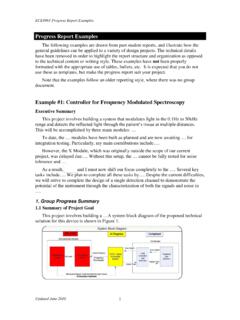
8 To verify our imperceptibility requirement, we can measure .. between the original and watermarked image. To do this we will use .. to determine if the measured value is sufficiently We will run through some functional verification testing to ensure that all the inputs, menu options, and outputs are displaying and working correctly on the user interface. Updated September 14, 2007 !Hardware PROJECT Example !!!4 Technical Design Possible Solutions and Design Alternatives There are several key design criteria that must be considered when deciding on the final design for our For the signal processing hardware, the design criteria include the For the Graphical User Interface, the design criteria There are three main areas where major design variations are possible. The first is the type of algorithm used on the FPGA to analyze the data. The two alternative algorithms being considered The second possible implementation variation is the type of interface between the user s computer and the device System-level Overview The design is divided into three parts, namely the Optoelectronics Module, the Signal Processing Module and the Graphical User Interface (GUI) module.
9 The reflected light from, two distances to the source, will be analyzed for signal attenuation by realtime signal processing The GUI then displays the processed data to the clinician. Updated September 14, 2007 !Software PROJECT Example !!!4 Technical Design Possible Solutions and Design Alternatives 1. Coding the algorithm in Matlab/Java/C There are several strategies that we are exploring to implement the algorithm and interface. Developing the interface in Matlab would be advantageous Although Java can create more user-friendly GUIs and C can provide more processing power to handle high resolution images, the effectiveness of the algorithm may be mitigated when converted to Java or 2. Input Parameters Each sequence of input parameters determined by the user will result in unique false positive and false negative We may therefore have to specify only a few allowable input parameter values due to the sheer number of tests that would be required for too many parameter values.
10 The other option would be System-level Overview The secure watermark-based multimedia authentication system that we propose can be split up into two main processes: (1) Embedding the watermark onto the image:.. (2) Verifying a watermarked image:.. Updated September 14, 2007 !Hardware PROJECT Example !!!5 Module-level Descriptions Optoelectronics module: The purpose of the Optoelectronics module is to provide an interface to transmit light to the patient s tissue and to capture the reflected light using the photodetector The output of this module will be the converted electrical signals detected on each optical fiber the main components of this module are a laser diode board which generates the optical signal and a photodetector board which detects the attenuated optical signal. GUI module: The purpose of the GUI module is .. The module receives the following data from .. and outputs the following data to .. Assessment of Proposed Solution We believe this is the most effective system given the necessary trade-offs because it allows the most flexibility in future designs when the number of channels increases beyond 16 channels.