Transcription of Propeller Efficiency - NAR Associates
1 Propeller EfficiencyRule of ThumbDavid F. Rogers, PhD, ATPT heoretically the most efficient Propeller is a large diameter, slowly turning single bladepropeller. Here, think the Osprey or helicopters. In both cases, large diameter, slowly turn-ing, compared to typical fixed wing aircraft, propellers are used. Generally, single bladedpropellers are not used because of dynamic imbalance - think vibration. As a result, thegeneral wisdom is that better Propeller efficiency results from decreasing RPM. However, Propeller efficiency is not only a function of RPM. It is also a function of Propeller diam-eter and true airspeed. Generally these parameters are combined into a nondimensionalparameter called the advance ratio (J=V/ND), whereVis the true airspeed in feet persecond,Nis the Propeller rotational speed in revolutions per second andDis the propellerdiameter in feet.
2 Propeller efficiency also depends on the power coefficient, which is a function of, again,NandDand also density as well as the brake horsepower. Specifically, the power coefficient,Cp, is another nondimensional parameter defined byCp=BHP N3D5where BHP is the brake horsepower and (rho) is the local air density. From this, you cansee that simply saying lower RPMs give better Propeller efficiency is a bit simplistic. What is meant by a nondimensional parameter? Well, it is a parameter which, upon substituting thedimensions into the expression for each of the physical parameters, results in all the dimensions cancellingout, ,J=VND=V1N1D=ftsec1revsec1ft=ftsecsecrev 1ft=ftsecsec1ftBecause revolutions (rev) is not a physical dimension, the denominator in the second term is replaced witha blank. Finally, we haveJ=VND=ftsecsecft=ft/sec/sec/ft/and each of the physical dimensions cancels out, ,Jis 2010 David F.
3 Rogers. All rights reserved. Published by the American BonanzaSociety with Efficiency Cruise Rule of Thumb2 Furthermore, as with any aircraft, the designer has a design goal in mind. For theBonanza, the design goal was high speed cruise coupled with all around good handling andperformance. The design goal influences Propeller design and propellers are divided into three main categories: fixed pitch, adjustable (control-lable) pitch, both ground and in flight adjustable, and constant speed (RPM). Because ofwartime experience, Beech originally chose a controllable pitch Propeller for the Propeller diameter is principally influenced by ground clearance and tip speed(Mach number). Bonanza propellers started at 88 inches in diameter and, except for take-off, a maximum RPM of 2050. As maximum engine RPM increased, diameter decreased,because of tip Mach number, to 80 inches at 2700 RPM for a constant speed basic design philosophy for a constant speed Propeller is, for any selected enginepower, or torque, to change the pitch (angle) of the Propeller blades to absorb the selectedengine power, provided there is enough torque to turn the Propeller at the selected the blade pitch increases the blade drag, while decreasing the blade pitch de-creases the blade drag.
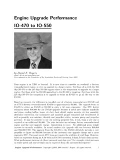
4 Hence, a larger (coarser) blade angle, for a given RPM, will absorbmore power and require more torque to turn it at the requested RPM. Similarly a smaller(finer) blade angle, for a given RPM, will absorb less power and require less torque to turnit at the requested blades are twisted from root to tip. The amount by which the blades aretwisted, along with the variation in chord, airfoil section and sweepback of the blade leadingedge, are design decisions. Those design decisions are significantly influenced by the designgoal. Even with a controllable pitch or constant speed Propeller , optimum design throughoutthe flight regime is not achievable. The design goal for the Bonanza is high speed , Propeller design and selection is optimum or near optimum for high speed , performance for takeoff and climb is Simplified Rule of ThumbFrom the Propeller maps for both the common two and three blade McCauley propellersfitted to the later Bonanzas, agenericpropeller efficiency curve, , (eta) as a function ofthe advance ratio,J, can be estimated as shown in Figure 1.
5 For full power and 2700 RPMat sea level and for 65% power at 6000 ft at 2300 RPM, the maximum Propeller efficiencyoccurs for betweenJ= andJ= as shown by the gray band in Figure Ratio, JPropeller efficiency, Figure Propeller efficiency vs advance 2010 David F. Rogers. All rights reserved. Published by the American Bonanza Society with Efficiency Cruise Rule of Thumb3 Outside of these values the Propeller efficiency decreases. From this, we can see that, for afixed diameter Propeller , it is the ratio of the true airspeed to the Propeller RPM that isimportant in achieving maximum this generic Propeller efficiency curve the ratio of RPM/TAS should be maintainedat approximately 15 to give an advance ratio ofJ= , ,J=VND= KTAS(RPM/60)(D/12)=(60) ( ) (12) KTAS(RPM) (D)= the converts KTAS (knots true airspeed) to ft/sec TAS, the 60 converts RPM toRPS (revolutions per second) and the 12 converts inches to feet.
6 For a Propeller diameterof 80 inches, after rearranging and inverting this equation, we haveRP MKTAS= a rule of thumb to maintain maximum Propeller efficiency. However, this is a rule ofthumb so let s use for A Simplified Rule Of Thumb (ASROT). It is easier to rememberand close Tuning the Rule of ThumbThe Propeller efficiency curve shown in Figure 1 is a composite of both the typical Bonanzatwo and three blade propellers at two different conditions. Is there a way to fine tune therule of thumb for a specific aircraft and Propeller ? Because the Bonanza design goal washigh speed cruise, it is reasonable to assume that the factory Propeller is optimized forthat a practical matter, for a normally aspirated engine the cruise true airspeed increaseswith altitude until the critical altitude for a given power setting is reached. Let s call thecritical altitude the knee in the curve.
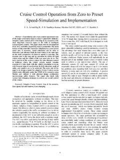
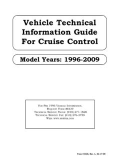
7 Above the knee the engine can no longer producethe requested percentage of power. High speed cruise conditions for various altitudes andpower settings are represented by the altitude vs cruise airspeed graph (see Figure 2) inthe performance section of the Pilot Operating Handbook (POH). As examples to test theASROT let s use the knee in the altitude vs cruise true airspeed graph from the 1 Cruise Airspeed EfficienciesAltitude %BHP BHP RPM KTASJCp SymbolASROT6000 Red Blue Green Black Red = 3100 lbs, standard dayTable 1 illustrates the results for the power settings, altitudes and airspeeds correspond-ing to the knee in the cruise true airspeeds vs altitude curves represented by the dashed linein Figure 2 obtained using the bare Propeller efficiency map for the C76 McCauley 3-blade80 inch Propeller , as shown in Figure 3.
8 Table 1 shows that the advance ratio,J, lies onthe plus side of the to maximum efficiency curve at the higher true airspeeds and Pronounced AS ROT Bare Propeller efficiencies do not consider blockage effects of the nose or nacelles. For a properly designedpropeller blockage effects candecreasepropeller efficiencies by 1-3%.Copyrightc 2010 David F. Rogers. All rights reserved. Published by the American Bonanza Society with Efficiency Cruise Rule of Thumb4120130140150160170180 True Airspeed (knots)0246810121416 Pressure Altitude (1000 ft) (45%MCP)156 BHP-2100 RPM(55%MCP) (65%MCP) (75%MCP)FullThrottle-2100 RPMFullThrottle-2300 RPMFullThrottle-2500 RPME33 AWeight 3100 lbsISA StandardFigure This implies that an ASROT factor of 15 over-estimates the required RPM. Thelast column in Table 1 shows the ASROT factor required to obtain the stated RPM at thestated KTAS, , the RPM in column 4 divided by the KTAS in column 5.
9 The resultshows that the ASROT factor for this Propeller should be adjusted downward. A reasonableadjusted ASROT factor of is coefficient, CpAdvance ratio, J = efficiency, .. Knee cruise value6000750087001400011000 Alt (ft)BHP %7565554545 RPM25002300210021002100 Figure 3. McCauley C76 Propeller 2010 David F. Rogers. All rights reserved. Published by the American Bonanza Society with Efficiency Cruise Rule of Thumb5 Table 1 also shows that typically for higher KTAS higher RPM is required to maintainmaximum Propeller efficiency, while for lower KTAS lower RPM is required to maintainmaximum Propeller efficiency. This result confirms the current wisdom that lower RPM forlower true airspeeds increases Propeller now to the C76 Propeller map shown in Figure 3, notice the clustering of all ofthe high speed cruise data from 6000 to 14,000 ft. In fact, Figure 3 and Table 1 illustratethat the difference in Propeller efficiency is at most a little over1/2%.
10 This suggests thatusing the knee values from Figure 2 is a reasonable way to fine tune the ASROT valuefor a particular Propeller . It also indicates that being a little off in either RPM orJisnot , be aware that determining the specific RPM and manifold pressure that willgive near optimal Propeller efficiency for any given flight condition is an iterative on to Figure 3, we ll be coming back to it when we look at take-off, climb andturbonormalized 2010 David F. Rogers. All rights reserved. Published by the American Bonanza Society with permission.