Transcription of Propeller Geometry: Terms and Definitions
1 WORLD LEADERS IN PROPULSION AND MARINE MANEUVERABILITY SYSTEMS 1501 BUCHANAN AVE., GRAND RAPIDS, MI 49507 USA PHONE: (616) 452-6941 FAX: (616) 247-0227 PROPGEOM. 31 AUG00 MICHIGAN WHEEL ENGINEERING JJE PAGE 1 OF 18 Propeller Geometry: Terms and Definitions Master Document August 2000 Propeller GEOMETRY: Terms AND Definitions PROPGEOM.
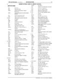
2 31 AUG00 MICHIGAN WHEEL ENGINEERING JJE PAGE 2 OF 18 Table of Contents Purpose Table of Symbols Section 1: Propeller Geometry Definitions General Features Pitch Skew, Rake, and Cup Blade Outlines and Areas Blade Sections Blade Edge and Hub Details Section 2: Conventions and Discussion Coordinate Systems Pitch Skew, Rake, and Cup References Propeller GEOMETRY: Terms AND Definitions PROPGEOM.
3 31 AUG00 MICHIGAN WHEEL ENGINEERING JJE PAGE 3 OF 18 Purpose This document provides standard Definitions for marine screw Propeller geometry terminology and associated characteristic descriptions. This standardization is an attempt to clearly define the complex nature of Propeller geometry and thus foster efficient, knowledgeable communication. Section I of this document presents pure, general Definitions of Terms associated with Propeller geometry. The approach is to move from the obvious physical features of a Propeller to a more detailed level that describes properties just as important, but perhaps somewhat more difficult to see.
4 Section II describes various conventions for defining geometric properties. The presentation is objective and makes no recommendations as to which methods are most accurate or appropriate. The aim is to uncover the different interpretations of common Terms and establish a clear understanding of the importance of standardization in Propeller geometry terminology. Table of Symbols C Chord length rh Radius near the hub D Diameter rt Radius near the tip h Drop height Swept Angle LE Leading edge PCA Propeller Center Axis P Pitch
5 BCA Blade Center Axis R Radius PCL Propeller Centerline TE Trailing edge BCL Blade Centerline Geometric pitch angle h Geometric pitch angle near the hub t Geometric pitch angle near the tip Propeller GEOMETRY: Terms AND Definitions PROPGEOM.
6 31 AUG00 MICHIGAN WHEEL ENGINEERING JJE PAGE 4 OF 18 Propeller Geometry: General Features reference Figure for the following Terms . No. TERM DEFINITION 1. Diameter The diameter of the imaginary circle scribed by the blade tips as the Propeller rotates. 2. Radius The distance from the axis of rotation to the blade tip. The radius multiplied by two is equal to the diameter. 3. Blade Face Pressure Side, Pitch Side. Aft side of the blade (surface facing the stern).
7 4. Blade Back Suction Side. Forward side of the blade (surface facing the bow). 5. Leading Edge The edge of the Propeller blade adjacent to the forward end of the hub. When viewing the Propeller from astern, this edge is furthest away. The leading edge leads into the flow when providing forward thrust. 6. Trailing Edge The edge of the Propeller adjacent to the aft end of the hub. When viewing the Propeller from astern, this edge is closest. The trailing edge retreats from the flow when providing forward thrust. 7. Blade Number Equal to the number of blades on the Propeller . 8. Blade Tip Maximum reach of the blade from the center of the hub.
8 Separates the leading and trailing edges. 9. Hub Solid cylinder located at the center of the Propeller . Bored to accommodate the engine shaft. Hub shapes include cylindrical, conical, radius, & barreled. 10. Blade Root Fillet area. The region of transition from the blade surfaces and edges to the hub periphery. The area where the blade attaches to the hub. 11. Rotation (Right hand shown here) When viewed from the stern (facing forward): Right-hand propellers rotate clockwise to provide forward thrust. Left-hand propellers rotate counter-clockwise to provide forward thrust. Figure Propeller GEOMETRY: Terms AND Definitions PROPGEOM.
9 31 AUG00 MICHIGAN WHEEL ENGINEERING JJE PAGE 5 OF 18 Propeller Geometry: Pitch reference Figures , , and for the following Terms . No. TERM DEFINITION 1. Pitch The linear distance that a Propeller would move in one revolution with no slippage. 2. Cylindrical Section A cross section of a blade cut by a circular cylinder whose centerline is the Propeller axis of rotation. 3. Pitch reference Line reference line used to establish the geometric pitch angle for the section.
10 This line may pass through the leading and trailing edges of the section and may be equivalent to the chord line. See Item No. 4 of Section 4. Geometric Pitch Angle, The angle between the pitch reference line and a line perpendicular to the Propeller axis of rotation. 5.* Controllable Pitch Propeller The Propeller blades mount separately on the hub, each on an axis of rotation, allowing a change of pitch in the blades and thus the Propeller . 6.* Fixed Pitch Propeller The Propeller blades are permanently mounted and do not allow a change in the Propeller pitch. 7.* Constant Pitch Propeller The Propeller blades have the same value of pitch from root to tip and from leading edge to trailing edge.