Transcription of PROPELLER WALL - Loren Cook Company
1 1 PROPELLER WALL IO&MB51091-003 Rotating Parts & Electrical Shock Hazard:Fans should be installed and serviced by qualified person-nel electric power before working on unit (prior to removal of guards or entry into access doors).Follow proper lockout/tagout procedures to ensure the unit cannot be energized while being installed or disconnect switch should be placed near the fan in order that the power can be swiftly cut off, in case of an emer-gency and in order that maintenance personnel are provid-ed complete control of the power is required. All field-installed wiring must be completed by qualified personnel. All field installed wiring must comply with National Electric Code (NFPA 70) and all applicable local and blowers create pressure at the discharge and vacuum at the inlet. This may cause objects to get pulled into the unit and objects to be propelled rapidly from the discharge. The discharge should always be directed in a safe direction and inlets should not be left unguarded.
2 Any object pulled into the inlet will become a projectile capable of causing serious injury or air is allowed to move through a non-powered fan, the impeller can rotate, which is referred to as windmill-ing. Windmilling will cause hazardous conditions due to unexpected rotation of components. Impellers should be blocked in position or air passages blocked to prevent draft when working on and power loss inside rotating components will cause them to be a potential burn hazard. All components should be approached with caution and/or allowed to cool before contacting them for certain lighting conditions, rotating components may appear stationary. Components should be verified to be stationary in a safe manner, before they come into con-tact with personnel, tools or to follow these instructions could result in death or serious attachment of roof mounted fans to the roof curb as well as the attachment of roof curbs to the building struc-ture must exceed the structural requirements based on the environmental loading derived from the applicable build-ing code for the site.
3 The local code official may require variations from the recognized code based on local data. The licensed engineer of record will be responsible for pre-scribing the correct attachment based on construction ma-terials, code requirements and environmental effects spe-cific to the and Inspection Carefully inspect the unit and accessories for any dam-age and shortage immediately upon receipt of the unit. Turn the PROPELLER by hand to ensure it turns freely and does not bind Record on the Delivery Receipt any visible sign of damageXLWHPROPELLER WALLP ropeller Wall Fans INSTALLATION, OPERATION AND MAINTENANCE MANUAL This publication contains the installation, operation and maintenance instructions for standard units of the PROPELLER Wall Fans. XWD XWHD XPD XPHD XLW / XMW XLWH / XMWH XLP / XLPH XMP / XMPH AWD AWB APD APB EWD EWB EPD EPB SWD SPB SPD Exhaust & Supply modelsCarefully read this publication and any supplemental documents prior to any installation or maintenance Cook catalog, PROPELLER Wall, provide additional information describing the equipment, fan performance, available accessories and specification additional safety information, refer to AMCA Publica-tion 410-96, Safety Practices for Users and Installers of Industrial and Commercial of the publications listed above can be obtained from: 417-869-6474 ext.
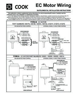
4 166 For information and instructions on special equipment, contact Loren Cook Company at WALL IO&MB51091-003 OFFSETANGULAROFFSET/ANGULARAWXYZBCENTERD ISTANCE(CD)GAPGAPT oleranceCenter DistanceMax GapUp through 12 1/16 12 through 481/8 Over 48 1/4 The drawing below indicates where to measure the al-lowable gap for the drive alignment tolerance. All contact points (indicated by WXYZ) are to have a gap less than the tolerance shown in the table. When the pulleys are not the same width, the allowable gap must be adjusted by half of the difference in width. Figure 3 illustrates using a car-penter s square to adjust the position of the motor pulley until the belt is parallel to the longer leg of the the fan into the wall opening and secure with lag screws, anchor bolts, or other suitable fasteners. Always mount belt drive wall fans in order that the motor base is below the fan shaft. WiringNOTICE! Correctly label the circuit on the main power box and always identify a closed switch to promote safety ( , red tape over a closed switch).
5 All wiring should be in accordance with local ordinances and the National Electrical Code, NFPA 70. Ensure the power supply (voltage, frequency, and current carrying ca-pacity of wires) is in accordance with the motor the wiring diagram in the disconnect switch and the wiring diagram provided with the enough slack in the wiring to allow for motor move-ment when adjusting belt tension. Some fractional motors have to be removed in order to make the connection with the terminal box at the end of the Fans1. Extend wires to the Prevent excess wire from entering the shaft and pro-peller area by restraining the excess wire to a point outside the Fans with Wire Guard1. Remove end panel from the wire guard to gain access to the Extend wires through a side panel of the wire guard to gain access to the Prevent excess wire from entering the shaft and pro-peller area by restraining the excess wire to a point outside the PROPELLER wall fans by attachment to the power !
6 Never lift by the shaft, motor or If the fan is stored for any length of time prior to installa-tion, coat the shaft with grease or a rust preventative com-pound. Store it in its original shipping crate and protect it from dust, debris and the the wheel several revolutions every three to five days to keep a coating of grease on all internal bearing mounted to a wall require a different wall opening size than fans mounted in wall collars or wall housings. For specific dimensions, refer to the submittal drawing for the specific fan InstallationTo prevent damage to the fan during shipping, motors 5 HP and larger, and extremely heavy motors (cast iron or severe duty) are shipped loose and must be field mounted by bolting the motor on the motor mounting plate in the existing slots. The motor should be mounted in order that the motor plate is between the fan shaft and the motor Remove the motor plate mounting bolts and motor Remove the motor mounting bolts from the motor Mount the motor to the motor plate aligning the appropriate Place the motor plate on the power assembly and reinstall the mounting and Pulley InstallationBelt tension is determined by the sound of the belts when the fan is first started.
7 The belts will produce a loud squeal, which dissipates after the fan is operating at full capacity. If belt tension is too tight or too loose, lost efficiency and damage can occur. Do not change the pulley pitch diameter to change ten-sion. The change will result in a different fan Loosen the motor plate adjustment nuts on motor base and move motor plate in order that the belts can easily slip into the grooves on the pulleys. Never pry, roll, or force the belts over the rim of the pulley. 2. Adjust the motor plate until proper tension is reached. For proper tension, a deflection of approximately 1/4 per foot of center distance should be obtained by firmly pressing the belt. See Figure Lock the motor plate adjustment nuts in place. 4. Ensure pulleys are properly aligned. See next AlignmentPulley alignment is adjusted by loosening the motor pulley setscrew and by moving the motor pulley on the motor foot1/4 inchFigure 1 Figure 23 PROPELLER WALL IO&MB51091-0032 Speed, 1 Winding, 3-Phase MotorMotor123456 TogetherHigh SpeedLineL1L2L3123456 OpenLow SpeedLineL1L2L3 MotorTo reverse, interchange any two line leads.
8 Motors require magnetic Speed, 2 Winding, 3-PhaseL1T1T2T3 Low SpeedLow SpeedLow SpeedHigh SpeedHigh SpeedHigh SpeedMotorT13T12T11L2 LineL3To reverse: High Speed: interchange leads T11 and T12; Low Speed: interchange leads T1 and T2; Both Speeds: interchange any two line Damper Motor SchematicFanMotorDamperMotor*SecondDampe rMotorTransformer**Transformer**L3L2L1 For 3-Phase, damper motor voltage should be the same be-tween L1 and L2. For single phase application, disregard L3.*Damper motors may be available in 115, 230 and 460 volt models. The damper motor nameplate voltage should be verified prior to connection.**A transformer may be provided in some installations to cor-rect the damper motor voltage to the specified your fan is supplied with a shutter, follow the direction below. If your fan is not supplied with a shutter, proceed to Final Installation ensure long-life, make a weather-proof seal by using a good quality silicon caulking under the shutter Place the shutter into the wall Mount the shutter to the supporting surface using Number 12 sheet metal screws on six inch centers around the Manually operate the shutter to ensure the blades move Fans with Wall Housing1.
9 Remove end guard from the wall Drill a hole through either side panel at a convenient location and pull the wires through. Do not pull wires through wire guard at the back Restrain the incoming wire at the side panel to pre-vent excess wire from entering the shaft and propel-ler DiagramsSingle Speed, Single Phase MotorT-1T-4 Ground BL2L1 Ground ALineWhen ground is required, attach to ground A or B with No. 6 thread forming screw. To reverse, interchange T-1 and Speed, 2 Winding, Single Phase MotorGround AGround BT-1T-4 Low SpeedHigh SpeedL1L2 LineWhen ground is required, attach to ground A or B with No. 6 thread forming screw. To reverse, interchange T-1 and T-4 Speed, Single Phase, Dual VoltageGround BJ-10T-5 Ground ALink ALink BLow VoltageLineL2L1 Ground ALink Aand BL1L2 LineGround BT-5J-10 When ground is required, attach to ground A or B with No. 6 thread forming screw. To reverse, interchange T-5 and J-10 , 9 Lead Motor456172839L1L2L3456789123L1L2L3 Low Voltage208/230 VoltsHigh Voltage460 Volts3 Phase, 9 Lead MotorY-Connection716789456123 Low Voltage208/230 VoltsHigh Voltage460 Volts824935L1L3L2L1L3L23 Phase, 9 Lead MotorDelta-ConnectionTo reverse, interchange any two line WALL IO&MB51091-00330 Minute IntervalInspect bolts, setscrews, and motor mounting bolts.
10 Adjust and tighten as Hour IntervalInspect belt alignment and tension. Adjust and tighten as Hour IntervalInspect belt tension. Adjust and tighten as a schedule for inspecting all parts of the fan. The frequency of inspection depends on the operating conditions and location of the fan. Inspect fans exhausting corrosive or contaminated air within the first month of operation. Fans exhausting con-taminated air (airborne abrasives) should be inspected ev-ery three months. Clean the PROPELLER and air inlets if ma-terial build-up is excessive. Excessive build-up can cause imbalance and failure of the PROPELLER . Regular inspections are recommended for fans exhausting non-contaminated air. It is recommended the following inspections be con-ducted twice per year. Inspect bolts and setscrews for tightness. Tighten as necessary Inspect belt wear and alignment. Replace worn belts with new belts and adjust alignment as needed. See Belt and Pulley Installation, on page 2 Bearings should be inspected as recommended in the Conditions Chart, page 5 Inspect for cleanliness.